The CANbus and CANopen protocol is a key technology for complex control tasks
BY URS KAFADER
Maxon Precision Motors
Fall River, MA
http://www.maxonmotorusa.com
Developers of complete systems with motor drives, sensors, and I/O are looking for standardized and simple interfaces to subsystems. They need decentralized solutions with tasks distributed to semi-autonomous units coordinated using a fieldbus. Modular assembly and standard components help speed development time, lower integration costs, provide flexibility, and simplify maintenance and adjustments.
Implementing this concept requires technology for motor drives that can cater to differently sized loads in one tool in a standardized way. For example, the 6-mm dc motor with a 1-W power rating obeys the same motion commands as the 60-mm-diameter 400-W EC motor or the 5-kW asynchronous machine. And, electronic synchronization of motors helps create a more flexible tool with arbitrary reduction ratios.
In most cases, it is difficult for low-powered motor drives (a few hundred watts or less) to be part of this concept, as they often have a proprietary control approach, making it harder for large and small drives to be integrated into a system, particularly mobile battery-powered ones. An alternative solution uses a standardized CAN fieldbus system for low-powered drive systems. It addresses performance issues such as coordination time for several axes.
One example
An example system is Maxon’s EPOS product. It uses the CANopen low-cost fieldbus, which features minimum cabling requirements.

Fig. 1. EPOS P is a programmable positioning controller and power stage for brushless and brush dc motors.
CANopen is widely used and is supported by many manufacturers. Its responsive nodes (up to 127) far exceed the requirements for most applications. CANopen can handle large segments, is real time compatible, and supports the synchronization of several axes. Performance is limited only by the maximum bit rate in CANopen networks. For motor drives in the low-output ranges and with the axes close to each other, a bit rate of 1 Mbit/s or 800 kbits/s can be used in most cases.
Miniaturization of the mechanically stable controller allows decentralized assembly close to the drive, reducing cabling and simplifying mobile applications. The drive’s digital and analog I/O can handle switch inputs and temperature or other sensors. EPOS motion controllers support an output range of 1 to 700 W.
Performance aspects
Two main application areas can be covered with the CANopen communication profile and CAN fieldbus: (1) multiaxis systems networked with nodes that are controlled point to point and (2) multiaxis systems with 2 to 10 axes that work synchronously. Limiting factors include:
A maximum of 127 nodes, such as axes.The highest bit rate of 1 Mbit/s can only be used if the bus is no longer than 25 m.A full CAN-frame with 8-data-byte (=64 bit) content typically requires a total of 130 µs, from one node to another. Lower data content requires a shorter transmission time.
Basic performance considerations apply to systems featuring several axes that are time independent and controlled on a point-to-point basis. For instance, the Controlword (2 bytes) and Targetposition (4 bytes) must be sent to start a positioning movement. The position report is, in turn, received in the Statusword, which is 2 bytes. The minimum communication time for an axis is therefore as follows:
Receiving a CAN frame (Rx PDO) with 6 data bytes: approx. 114 µs.Sending a CAN frame (Tx PDO) with 2 data bytes: approx. 82 µs.
If a customer assumes a maximum permitted bus load of 80%, time load on the bus is at least 250 µs/axis and movement, rising if other process data are sent.
Multiple axis sync
Applications are also possible where all axes are started simultaneously. This is easily achieved through configuring process data, and the previous timing number can even be reduced. In the quickest instance, a mechanical movement still lasts some 10 ms. The calculated communication time is short compared to the period that an axis needs to carry out a movement, and does not represent a restriction.

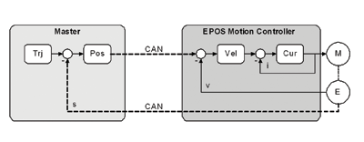
Fig. 2. Control loop closed via CANbus with loop speed specified by the master.
The much more challenging apps for a motion controller are those where several axes must be synchronized. Here individual axes need the CANbus to perform at full capacity many times over, as the control loops are closed via the bus. As shown in Fig. 2 , the master is responsible for path planning (Trj) and positioning control (Pos). The lower-level EPOS motion controllers work as speed controllers (Vel) with a subordinate current controller (Cur). The actual values measured by the encoder (E) reflect the motor position and are sent to the master by EPOS.
The synchronization method that CANopen DS301 ensures means that the control loops of the individual axes can be closed via the bus, that all axes adopt the new set value at the same time, and that the actual values are sensed at exactly the same time.
The CANopen master generates a SYNC telegram for every network participant to measure and send back the actual values. At the same time, the participant is required to activate the new set value sent during the last cycle time.
Set and actual values are again conveyed with Rx and Tx PDOs, along with Controlword and Statusword. Below is a calculation example with three axes at a 1 Mbit/s rate:
SYNC command: 66 µs.Actual position values for three axes: 342 µs (3 x 114 µs).Set speed values for three axes: 342 µs (3 x 114 µs).Total: 750 µs.
A minimum cycle time of 1 ms is suitable for three axes based on maximum bus capacity. Experience shows that even for small and highly dynamic motors, cycle times greater than 5 ms are problematic. Up to 10 axes can thus be synchronized, if the master can carry out the necessary calculations quickly enough.
Example: EOD robot
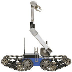
Using EPOS with Maxon motors, Telerob (www.telerob.de) has developed a remote-controlled EOD robot to investigate dangerous areas and diffuse explosives. CANbus communicates with the modules. The CANopen protocol was crucial in speeding the robot’s development and making it more modular. The axes are largely controlled on a time-independent basis, which means the bus performance easily meets requirements. Fieldbus allows submodules, such as a prehension arm or drive, to be used for other products and helps simplify the use of mechanical interfaces.

Fig. 3. A remote-controlled EOD robot was developed by Telerob to investigate dangerous areas and diffuse explosive charges.
The largest of the drives used are in the four drive tracks, each fitted with a 40-mm-diameter dc motor with brakes and encoder. Smaller motors with sensors are used in the seven-axis manipulator with an adjustable tower. A total of nine drives in the 5 to 150-W output range are used.
CANbus links the EPOS controllers, and a real-time computer is used as the master system, controlling not only the drives but also the operation terminal and camera. Information is transmitted via a radio interface. The four-chain drive, axis manipulator, and tool change system are served by the operation terminal. The EOD robot is battery powered and can be used completely autonomously for a wide range of tasks, thanks to its high efficiency. ■
Advertisement
Learn more about Maxon Precision Motors


