Cap-discharge resistors stabilize PFC operation
High-voltage, high-power resistors discharge the dielectric fluid-filled capacitors used in PFC applications
BY MARTIN BIRKETT
Senior Applications Engineer
TT electronics Welwyn Components
www.ttelectronics.com
Power factor correction is a very popular and well-established technique for reducing the overall energy consumption of electrical systems including power lines, transformers, motors, and other high-inductive loads. In addition to reducing the energy costs and the carbon footprint, this technique reduces voltage drops, increases the service life by reducing heating, and reduces losses through the Joule effect.
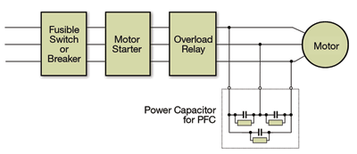
The most common and simplest method of power factor correction in large inductive loads is to install compensating capacitors on the network close to the load (see Fig. 1 ). These capacitors need to be discharged when the power is turned off if they are not to become a safety hazard. New ranges of high-voltage discharge resistors are being introduced for this purpose, which not only can handle the high levels of continuous power associated with this application, but also offer excellent short-term overload performance if a fault occurs.

Fig. 1: A typical power factor correction Installation.
Medium-V capacitors for PFC
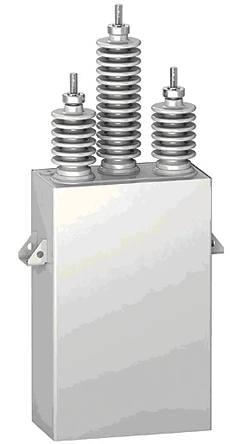
Medium-voltage capacitors typically operate from 5 to 25 kV. They are constructed from a set of capacitor elements, each with its own fuse, wired in series and parallel groups, and fitted inside a dielectric fluid-filled metal enclosure with terminals on top (see Fig. 2 ).

Fig. 2: A medium-voltage capacitor is constructed from a set of capacitor elements, each with its own fuse, wired in series and parallel groups, and fitted inside a dielectric fluid filled metal enclosure with terminals on top.
One of the most important aspects of the capacitor design is the provision of a quick and safe discharge when the electricity is turned off.
The capacitors can hold large charges, which, if left to self-discharge, allow dangerous voltages to remain for long periods of time, presenting potential safety hazards for service personnel. The discharge of 0.25 J of stored energy to the human body can provide a heavy shock, and 10 J can be fatal. Therefore one of the most critical components of the capacitor banks is the high-voltage discharge resistor, which reduces the residual voltage of the capacitor to a safe working level at turn off. According to IEC 831 this should be below 75 V after 3 min.
Discharge resistor requirements
In addition to providing a quick and safe discharge of the capacitor, a suitable resistor for this application must meet several other important requirements.
First, as the resistor is enclosed in the capacitor housing it is not practical to switch it in to the circuit for discharge. It must be permanently connected and therefore be able to operate continuously at the rated power for the lifetime of the capacitor. Moreover, the resistor must be able to handle high voltage overloads up to 25 kV during fault conditions, which, due to the relatively low resistance values required in this application (100 kΩ to 10 MΩ), can be in excess of 150 W per resistor. Therefore the device must be able to handle a combination of high voltage and high power.
Second, as the capacitor housing is completely filled with dielectric fluid, the resistor must be chemically compatible, and not cause any pollution that could affect the reliability of the capacitor.
Finally, as the resistor will normally be hand soldered to the capacitor electrodes and will be immersed in the dielectric fluid, its terminations need to be very robust to withstand any vibrations during the life of the capacitor.
Case study
There are many commercially available high-voltage resistors and high-power resistors. The combination, however, especially on a small planar footprint, presents significant challenges. Add to this the requirements for chemically compatible materials and robust terminations, and the design becomes quite challenging. TT electronics has addressed these challenges for a manufacturer of medium-voltage capacitors.
High-voltage resistors are typically made with high-resistivity inks, which have excellent voltage-handling capabilities and are printed in long meandering patterns to reduce the voltage stress. Because the discharge resistors have relatively low values, they must be manufactured using low-resistivity inks with reduced voltage-handling capabilities. The resistor pattern then can be optimized to give maximum length to improve voltage handling without jeopardizing creepage and clearance distances.
The overload-power-handling capabilities can be optimized by using a high-alumina substrate of increased thickness to dissipate the heat into the capacitor’s dielectric fluid.
Once the resistor design is finalized, a method of trimming it to target value is required. Because of the large voltage gradient across adjacent limbs of the resistor pattern, the position and cut width of the laser trim links needed to be optimized to reduce the voltage trying to arc across the cut during overload conditions. To achieve this, a proprietary cut method is used, which uses the momentum of the laser to achieve maximum cut width in minimum time.
After trimming, the resistor is protected with a special screen-printed material. This function requires the use of a high-temperature firing glaze, as low-temperature curing materials have been found to pollute the capacitor’s dielectric. However, high temperature in turn can cause problems with shifts in resistor value during firing, which must be compensated.
Another issue with the glaze is its insulation resistance during overload conditions. As the glaze has a large negative TCR, its insulation resistance can decrease when the resistor heats up and create a path for the high voltage to arc. It is critical to select a glaze with high insulation resistance and ensure that no air is trapped during processing.
Finally, increasing the strength of the terminations can be accomplished by increasing the solder pad area and using a larger diameter lead wire. While this approach presents a challenge in fitting the resistor pattern in the remaining substrate area, this can be solved by optimizing the design and using resistor materials with good voltage-handling performance.
CDR series
In light of the increasing popularity of power factor correction to reduce energy consumption, resistor manufacturers are responding with new ranges of high voltage resistors specifically designed to discharge the dielectric fluid filled capacitors used in power factor correction applications.
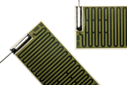
For example, the TT electronics CDR series combines a unique high-voltage resistor design with high-power-handling materials to give excellent short-term overload performance during fault conditions, while also handling the required continuous power levels (see Fig. 3 ).

Fig. 3: The capacitor discharge resistors (CDR series) combines a high-voltage resistor design with high-power-handling materials to give excellent short-term overload performance during fault conditions.
It also has high-strength terminations giving exceptional reliability during vibrations and is protected with specially formulated glass, which does not pollute the capacitor’s dielectric fluid. The CDR is available in 1 to 10-W continuous-power ratings (100ºC in dielectric fluid) with a resistance value range of 100 kΩ to 10 MΩ. Overload power and voltage ratings are available up to 150 W and 25 kV, respectively.
Power factor correction is an excellent and low-cost way of reducing energy costs and achieving a range of other worthwhile design benefits. The discharge resistor is by no means a costly element in the context of the overall design, and it is well worth specifying a component that fully supports the envisaged continuous and overload powers, is able to tolerate the environmental conditions and has a sufficiently long service life. Make the right design choice at the outset, and the discharge resistor can become a “fit and forget” component. ■
Advertisement
Learn more about TT electronics IRC


