What they didn’t teach you in engineering school
BY DAVE VAN ESS
Application Engineer, MTS
Cypress Semiconductor
www.cypress.com
All in all, they have a lot of nerve calling a capacitor a “passive” component (it’s more like passive aggressive if you ask me). Like most of you, my first formal exposure to capacitors was in first year physics, then again in my first electronics class. I got even more in analog and fields and wave classes. In all cases, they were treated as ideal. THEY ARE NOT! I had to learn about real capacitors one mistake at a time. Here is what I have learned.
Capacitors are used for the following different areas. I will discuss the first three.
• Power supply decoupling.
• Analog filters.
• Calibration and node tweaking.
• Energy storage.
Power supply decoupling
One of the first designs I did right out of college was a digital board with a handful of small-scale-integrated (SSI) ICs: I built it up, and of course it failed to work. I asked one of the senior guys for help, and he asked where the bypass caps were. I naively said this was a digital design and didn’t need caps. He gave me a pained look and told me to go simulate a digital inverter with Spice. I did so and found that a significant pulse of current is required of the supply whenever the output transitions. The bypass cap allows this current to be supplied without impacting the supply.
For bypass caps, I prefer 0.01 to 0.1-µF Z5U ceramic caps. Z5U is an EIA class 2 dielectric that has a low cost, small size, and really rotten temperature stability, but capacitance change as a function of temperature is not important in bypass caps. They can easily be found in a range of values from 2200 pF to 3.3 µF. The only other important parameter is the rated voltage. A good rule of thumb is to get a cap with a rated voltage at least twice the supply voltage.
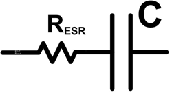
Besides local bypassing, there will need to be a bulk capacitance. Generally this is either tantalum or aluminum electrolytic capacitors. Both have polarity and can fail dramatically if a reverse polarity voltage is supplied. However, they pack a lot of capacitance into a given volume. Tantalum is the preferred capacitance because of its low equivalent series resistance (ESR). A model of the ESR is shown in Fig. 1 .

Fig. 1: The equivalent series resistance (ERS) limits the ability of a bulk capacitor to deliver or absorb current.
The purpose of the bulk caps is to supply or absorb pulses of current. For an ideal capacitor, its impedance to a step change is zero. This means a smaller tantalum cap can be used to replace an aluminum cap. Tantalum caps have better frequency characteristics, are generally smaller values, and are constructed from a dry process that does not degrade over time. Aluminum caps, for their part, are cheaper.
Rated voltage is important but so is the ripple voltage spec. With more switched regulators, the bulk capacitor is used to remove the ripple. The ripple is seen across the ESR resistor and causes heat. Excess heat will degrade a capacitor and cause premature failure. Think of the ripple as the sun, the ESR as a magnifying glass, and the capacitor as the poor bug. Too much heat, and something is going to die.
Analog filters
This is where things go nuts. You could use a poly cap (polypropylene, poly carbonate, polyester), ceramic, mica, glass, Teflon, foil capacitors, or film capacitors. It gets SOOO confusing. Well let me try to simplify it. Use NP0 and X7R ceramic capacitors. They will work most of the time. X7R capacitors are an EIA class 2 dielectric. They are slightly piezoelectric and are readily available in values from 100pF to 22 µF. They come in tolerances of ±5%, ±10%, and ±20%, with a variation over temperature (–55°C, 125°C) of ± 15%. NP0 capacitors are an EIA class 1 dielectric. They have negligible piezoelectric effect and are readily available in values from 1pF to 0.1 µF. They come in tolerances of ±1%, ±2%, ±5%, and ±10% (prohibitively priced below ±5%), with a variation over temperature of ± 30 ppm/ºC. The NP0 capacitors are more accurate but they are also more expense and are limited in maximum values. With 5% NP0 capacitors and 1% resistors, it is feasible to design multistage filters.
The limitation of ceramic caps is seen with filters with roll off frequencies below 1.5 Hz and high-resolution dual slope ADCs. This limitation is caused by dielectric absorption.
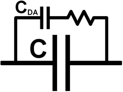
Dielectric absorption is the inability for a capacitor to release all its stored energy in a timely manner. Figure 2 shows a very simplified model of dielectric absorption.

Fig. 2: Very simplified dielectric absorption model.
The dielectric absorption (DA) value is defined as the ratio of these two capacitors and is expressed as a percentage. X7R ceramic capacitors have a DA of about 1% and are typically acceptable for filter values down to 1Hz. Below that and you will need a “poly” cap. Polyester and polycarbonate capacitors have a typical DA value of 0.2%. Polypropylene capacitors have a typical value of 0.1%. One solution is to use a very low DA capacitor. A polypropylene cap would be a good choice, but they are expensive and large, which limits moving your design to an integrated solution.
Since most likely the signal is going to be digitized, the analog integrator can be replaced with a DAC and a simple digital filter. The topology is shown below. Instead of buying an expensive cap, I prefer to replace it with an ADC and DAC. Figure 3 is a block diagram for a high-pass filter.

Fig. 3: A DAC and ADC replace a very large, very expensive capacitor integrator feedback high-pass filter.
Calibration and node tweaking
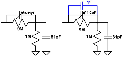
With passive dividers, the ac should have the same attenuation as the dc. An example of this is a scope probe shown in Fig. 4 .

Fig. 4: Exploiting circuit board capacitors allows for better sensitivity in calibration.
For the ac and dc attenuations to match dc, the cap across the 9-MΩ resistor should ideally be 9 pF. On the left, a wide range trimmer was used. An option is to use a smaller range trimmer and construct an on-board capacitor. This allows for three times the sensitivity.
Construction of board capacitors is a very powerful tool. A trick I learned for high common mode rejection circuits adjusts the capacitance on similar nodes to within 0.5 pF. The test I use is to imagine an impedance check bug sitting on a node. If it cannot determine which channel it is on, then your design will have superior common mode rejection.
Well, that’s it. 30 years of experience in a thousand words. Not very fast for a typist, but fast enough for an analog guy. ■
About the author
David Van Ess is a Applications Engineer and Member of Technical Staff at Cypress Semiconductor. He has 34 years of experience in circuit, signal processing, digital, software, and system design for such areas as commercial test and measurement equipment, automated robotic and manufacturing systems, radio equipment for logging applications, measurement and control systems for high energy physics research, ECC front ends for diagnostic, emergency, and implanted cardiac care equipment, and underwater acoustic transmitters and receivers deployed in open sea and artic ice fields.

He has nine U.S. Patents (plus a couple pending) for medical systems, signal processing, digital block enhancements, and PSoC ADC technology. Dave holds a BSEE from University of California, Berkeley.
Advertisement
Learn more about Cypress Semiconductor


