Challenges in parallel data acquisition systems for MRI
Parallel MRI allows the user to extract extra spatial information, which leads to a shorter acquisition time, higher resolution, extended field-of-view, and crisper image quality
BY GUGLIELMO SIRNA and VINOD PALIAKARA
Texas Instruments
www.ti.com
Today a whole body exam could involve up to 76 receiver chains and the current industry trend is to increase the channel count even further. The higher integration of high-performance analog functions will play a key role in solving the demands of parallel MRI system designs. This article presents the design tradeoffs in the architectural trends for compact MRI receivers.
Magnetic resonance imaging
Magnetic resonance imaging (MRI) is an advanced noninvasive diagnosis modality based on the principle of nuclear magnetic resonance (NMR).
Similar to a compass pointer that aligns with the Earth’s magnetic field, some nuclei in the body act as small magnets and, when placed into a strong magnetic field (Bo), they align their spin.
Many nuclei (in the low-energy state) align with the Bo direction, while a slightly smaller number of nuclei (in the high-energy state) align against it. Since a large portion of the human body is made up of water and fat, and both include hydrogen atoms, the most common MRI machines target the 1H protons. If the correct electromagnetic energy is applied, some protons will absorb the energy and change from a low to high (excitation) state. The amount of energy and frequency required depend on the intensity of the magnetic field and the nature of the nucleus. For hydrogen, the frequency is 42.58 MHz/tesla. MRI machines are built with Bo from 0.25 to 7 T, where 1.5 and 3 T are the most commonly used in clinical MRI.
The excitation signal consists of a complex sequence of radio frequency (RF) pulses, designed to provide the wanted image contrast. They are applied using tuned antenna coils placed in the proximity of the patient.
When the RF pulses cease, the excited protons return to the low-energy state (relaxation) by emitting energy at the same resonance frequency. The MRI receiver receives these relaxation emissions and transforms them into complex digital data for further image processing.
To precisely locate the spatial position of the emission, which is necessary to form a 2D or 3D image, the magnetic field strength is varied at different points of the body using the gradient coils. By doing so, different locations are subject to different magnetic field strength and the frequency and phase of the emission relate precisely to a specific location of the space.
Parallel MRI imaging
The amount of data necessary for reconstructing a quality image could be significant and the imaging speed is one important parameter for clinical MRI. To improve the acquisition time, modern MRI machines use parallel acquisition techniques, where local antennas are arranged around the patient’s body in a phase-array mode. These are often called surface coils.
Each surface coil is connected to a dedicated receiver chain where the RF signals are processed in parallel. Complex software algorithms extract additional spatial information from the antenna array and reconstruct the signals from multiple channels, reducing the image acquisition time dramatically. Faster scanning shortens the patient’s examination time, and increases the patient throughput.
Parallel imaging improves the field-of-view (FOV). The individual receiver covers only a small portion of the entire FOV. The data coming from each receiver can be recombined to reconstruct a full-FOV image. Optimal SNR can be achieved by multi-channel technology. Surface coils are more sensitive to signal in their proximity or FOV, and less sensitive to noise coming form other parts of the patient’s body.
The number of elements used in modern MRI scanners could be up to 76, and the number of channels in the next generation scanners is expected to grow. Even when using parallel imaging, each MRI receiver must continue to maintain the highest possible signal-to-noise ratio (SNR).
MRI receiver
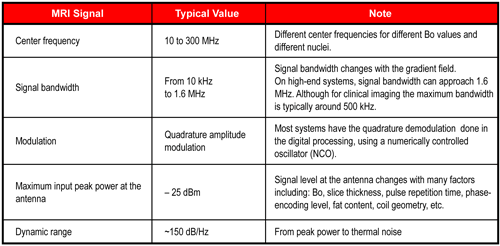
MRI signal characteristics depend on several parameters: the strength of the signal provides information on the density of protons; the frequency and phase provide the location; and the measurement of relaxation times discriminates between different tissues. The main characteristics of the MRI signal, at the receiver antenna coil, are described in Table 1.
The signal center frequency can be from 10 MHz to 300 MHz, depending on the different Bo strength.
Signal bandwidth changes with the strength of the gradient field and the selected FOV. Today typical gradient coils are capable of producing gradients from 20 mT/m to 100 mT/m, corresponding to a maximum signal bandwidth of around 1.6 MHz.

Table 1: Main characteristics of the MRI signal.
The challenge in MRI signal acquisition is to obtain high-quality images. This revolves mostly around the accuracy of overall signal processing. The MRI receivers are ultra-low-noise, they have a high SNR and high dynamic range (DR). The RF level at the antenna is low, and the minimum detectable signal is close to the thermal noise floor: –174 dBm/Hz at room temperature.
The noise figure (NF), which measures the degradation of the SNR introduced by the receiver, is primarily set by the first block of the chain: the preamplifier.
Available MRI preamplifiers have less than 0.5-dB noise figure. They are designed to reduce the available SNR by less than 5%. The SNR of the other blocks of the receiver chain, including the analog-to-digital converter (ADC), remain a key specification.
Under certain circumstances, the signal power at the antenna could reach –25 dBm. The preamplifier has to be very linear and its 0.1-dB compression point is typically greater than the maximum MRI signal power. For any operating conditions, a good MRI preamplifier should have less than 1% nonlinearity. After the preamplifier, the RF signal is processed in different ways, depending on the particular architectural choices of the various OEMs.
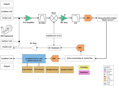
Traditional systems, shown in Fig. 1 use the heterodyne receiver with down-converting mixers. The mixer translates the RF signal band into a much lower frequency by multiplying it with a local oscillator. The conversion into digital data occurs at the baseband where the requirements of the ADC sampling frequency and the anti-aliasing filter are more relaxed.
An important drawback of the heterodyne receiver is that in addition to the wanted signal, they typically down-convert the unwanted noise of the image frequency into the baseband, ultimately reducing the available SNR. To suppress the image noise by at least 40 dB, the heterodyne receivers use image rejection filters (SAW or high-order discrete LC resonator) or complex image rejection mixers, which have an impact in the noise performance in the board space and power consumption.

Fig. 1: Block diagram of heterodyne MRI system.
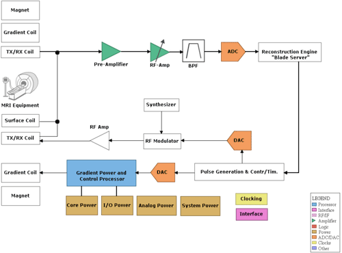
With the availability of high-performance ADCs, some new MRI systems are designed to directly sample the RF signal, as shown in Fig. 2 . Wideband RF amplifiers are combined with high-resolution (≥14-bit) and high-sample-rate ADCs (≥100 Msamples/s), capable of sampling the incoming RF signal directly.
Direct sampling is gradually replacing the heterodyne receiver since it eliminates the need for analog mixers and image rejection filters, partially reducing the receiver form factor. Of course, there are multiple design tradeoffs involved with this architecture, such as the need of high-frequency amplifiers and bandpass filters (BPF) to eliminate signal aliasing.
Power consumption and form factor are important constrains in recently designed MRI systems. Moving the receiver electronics closer to the coil area eliminates the need for long and bulky coax cables, running from the preamplifier outputs to the receiver inputs. Inside the coil area the available volume for the electronics and the ability to dissipate the heat are reduced.
A third important feature, for components mounted closer to the coil area, is the magnetic compatibility, or Bo disturbance. Any ferromagnetic material in the electronic component introduces an artifact in the image and, therefore, the components must be nonmagnetic.

Fig. 2: Block diagram of direct sampling MRI system.

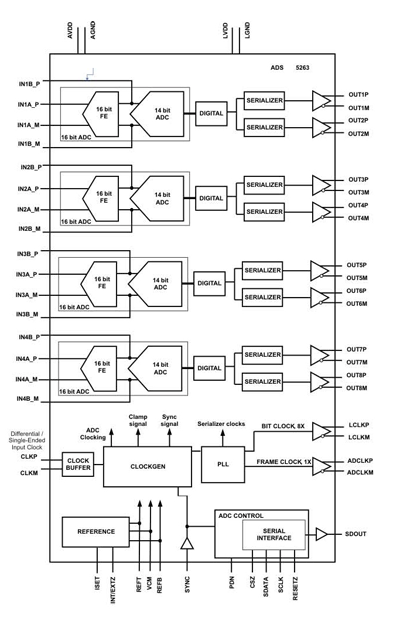
Fig. 3: Functional block diagram of a high-resolution ADC for medical imaging.
One good example of a compact high-performance ADC with low power and high level of integration is demonstrated by the ADS5263, a 16-bit quad-channel 100-MSample/s ADC with 380-mW/channel power and dual-LVDS outputs, shown in Fig. 3 .
Based on the pipeline architecture, this high-resolution ADC is designed to give very high SNR performance with a 4-Vp-p full-scale input. The device gives 86 dBFS SNR up to 10 MHz input, and better than 79 dBFS SNR up to 65 MHz input.
The 16-bit ADC consists of a low-noise first stage, followed by the rest of the stages that form a 14-bit ADC. The device also has a 14-bit low-power mode, where the 16 bit first stage is powered down. The part now operates as a 14-bit ADC, consuming almost half the power of the 16-bit ADC mode. The 14-bit mode supports 2-Vp-p full-scale input signal, with typical 74-dBFS SNR and 195-mW/channel power.
The ADS5263 can be dynamically switched between the two resolution modes. This allows systems to use the same part in a high-performance mode (16-bit ADC) or a low-power mode (14-bit ADC).
The four channels are packaged in a compact 9 x 9-mm2 nonmagnetic QFN package, allowing high system integration densities and perfect compatibility with high-field MRI systems that are prevalent nowadays.
Summary
The channel count in parallel MRI receivers is rapidly increasing. The design of modern MRI receivers will depend on the efficient integration of high-performance analog function, like the ADC, where the footprint and the power consumption are key specifications, together with high resolution, high SNR, and high sampling rate. ■
References
For more information about MRI designs, visit www.ti.com/medical-ca.
Download TI’s Medical Applications Guides: www.ti.com/medicalguides-ca.
About the Authors
Guglielmo Sirna, Medical and High-Reliability Systems Engineer at Texas Instruments, has more than a decade of product expertise which includes wireless transceiver, analog front-end and analog-to-digital converters. Through his role Guglielmo has developed a focused expertise on the design of analog front-ends for medical applications such as MRI, ultrasound and X-ray. Guglielmo received his MSEE from the University of Palermo, Italy. He can be reached at gsirna@list.ti.com.
Vinod Paliakara works as an Applications and Test Engineer at Texas Instruments. He has worked on a variety of mixed-signal front-end solutions for applications such as consumer medical, high-speed data converters and digital imaging systems. He can be reached at
.
Advertisement
Learn more about Texas Instruments


