Measuring inrush current can make the difference between a design’s success or failure, but has traditionally posed problems
BY BOB ZOLLO
Agilent Technologies
Budd Lake, NJ
http://www.agilent.com
R&D engineers have traditionally found it a challenge to measure dc inrush current and current during dc voltage transients because these measurements require complex setups with multiple pieces of equipment at minimum, and may even demand writing a program to control the setup, make the measurement, and capture the data. Furthermore, determining measurement accuracy usually means performing complex calculations to characterize a multiple-instrument system’s accuracy, and the transducers used for the test can interfere with the device under test’s (DUT’s) operation. What’s a designer to do?

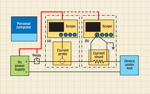
Fig. 1. A typical method of measuring dc inrush involves using either a current probe (a) or a shunt (b). The relay connected to the power supply can be omitted if the rise time of the power supply is fast enough.
What are the measurements?
Dc inrush current measurement determines how current flows into a DUT when dc power is first applied to it. This measurement involves rapidly applying a dc voltage (via a switch or a sharp voltage step) and then measuring the current that suddenly surges into the DUT using a scope.
A dc transient current measurement is similar, except that it takes into account the fact that a dc transient, such as a voltage surge or dropout, could occur anytime during the operation of the DUT, not just at power up. Creating a rapid change of voltage, either up from nominal for surge or down from nominal for dropout, could result in a rapid change of current flowing into the DUT, so making this measurement requires rapidly changing the dc input voltage, using a fast power supply, and then measuring the current going into the DUT with a scope as it changes in response to the transient.
Since the measurements are similar, only the dc inrush measurement will be discussed from here on. However, all the challenges associated with measuring dc inrush current apply to the dc transient current measurement.
There are four key reasons to measure dc inrush current: device characterization, fuse selection, battery sizing/drain, and dc adapter sizing.
For some DUTs, it may be important to measure the dc inrush just because it’s a specified parameter. For example, if you are purchasing an off-the-shelf dc/dc converter with a specified dc inrush current, you may make the measurement to ensure the converter meets spec, either as part of the vendor/part selection process or incoming inspection.
Fuse selection is affected by inrush current because the peak dc inrush current can be very large relative to the DUT’s normal operating current. For example, if a DUT has large capacitors on its input, large currents will flow as the capacitors charge when voltage is first applied.
Dc inrush currents can also be very large if a DUT has a complex power-up sequence, such as performing a power-on self-test, programming FPGAs, lighting lamps or backlights, or starting motors. Since any large inrush current could cause a fuse selected based on normal operating conditions to blow, designers need to characterize this current to properly size the fuse.
To provide the best operating experience for a battery-powered DUT, designers need to understand how dc inrush impacts battery performance. If peak current is high for a long time during startup, it can put a life-reducing drain on the DUT battery.
Furthermore, if the peak current is very high, even for a short time, the battery voltage can drop significantly due to battery internal resistance. This momentary drop in voltage can cause a DUT’s low-battery-detect circuit to engage and the DUT may unexpectedly shut down. The cause of this operating defect won’t be obvious unless you measure peak inrush current and see how it compares to normal operating current.
If the DUT is powered by a dc adapter (or charger), the peak inrush current can overload the charger, causing its voltage to collapse. So again, to properly size the dc adapter, you need to have a clear picture of the current profile during startup and normal operation.
Measurement challenges
The typical way to measure dc inrush current is to use a test setup in which a power source is applied to the input of the DUT (see Fig. 1 ). The power source could be a standard dc power supply with a relay on its output. To create a sharp edge, when the relay closes a voltage step is rapidly applied to the DUT. But if the power supply can generate a precise voltage step rapidly enough, no relay is needed.
At the moment the step change is applied, the current flowing into the DUT must be measured. An oscilloscopes is typically used to capture the current waveform and, since scopes can’t measure current directly, a current probe or shunt is needed.
While this measurement is conceptually simple, there are several challenges to making a dc inrush current measurement. For one, if your power supply can’t change fast enough and you choose to use a relay, you need to ensure that the supply has enough current capacity. If not, when the relay closes, the supply’s output capacitors will discharge and its voltage will collapse because the rapid application causes a load transient.
If the power supply can handle the load transient, then the next challenge is integrating the relay: either another piece of test equipment (like a relay box or switch-measure unit) or a custom-built relay. A custom-built relay will require design, mounting, and control, which can be very time consuming and distract from the main task: designing and characterizing your DUT.
To avoid relay hassles altogether, the power supply will need to have a fast rise time. If the rise time is slow, say 100 ms, the input of the DUT will see a voltage ramp, not the sharp-edged step change needed, and this could distort measurements and “soften” or reduce the peak current that you measure. Obviously, a manually controlled supply with knobs won’t work.
The scope used to make this measurement will need some way to detect peaks. Reading the peak off the graticule is inaccurate, so it’s best to have a scope with marker functions to detect peaks.
Alternatively, you can bring the scope trace data into a computer and analyze it, which would involve using a program to set up the scope, capture the waveform data, transfer it back to the PC, and then analyze it. If you want to capture the waveform image for use in a report, your scope will need some way to do thiseither an integrated floppy drive or a front-panel USB.
You may have to write a program to do all these things, although many scopes have PC utility programs to help. Still, using a PC adds extra steps to the test process.
Since scopes measure voltage, one way to measure current with a scope is to use a current probe, which can be inaccurate as well as expensive. Alternatively, a current shunt (or current-sense resistor) can be used, based on the theory that voltage drop across the shunt is directly proportional to inrush current.
Shunt issues
To get an accurate measurement, the value of the shunt resistance must be known precisely, but as current flows through the shunt, it will heat up and change its resistance value, making accurate measurement difficult. Also, most scope inputs are ground referenced, so connecting the scope grounds one side of the shunt, which might cause a grounding issue for the DUT.
Selecting the right shunt resistance value is another challenge. If it is too high, there will be a large voltage drop across the shunt as high current flows through the DUT, reducing the voltage at the DUT’s input. For a low-voltage DUT, such as a 1.2-V dc/dc converter found in cellular phones, reducing the input voltage by 50 or 100 mV causes improper operation. On the other hand, using a very-low-resistance shunt keeps voltage low at peak currents, but makes it hard to measure normal operating current.
Simpler test gear
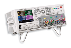
Alternative equipment for making dc inrush current measurements has recently appeared in the form of a new category of test instrument: the dc power analyzer. Highly integrated, the Agilent N6705A DC Power Analyzer (at left ) combines up to four modular dc power supplies with the functionality of a DMM, a scope, an arbitrary waveform generator, and a datalogger, with each instrument function behaving like its standalone counterpart. All the functions and measurements are available at the front panel, thereby eliminating the need for a PC, drivers, and software, and reducing 90% of the effort associated with setup.

Systems like the N6705A DC Power Analyzer ease inrush test.
Configurable from a choice of 21 dc power modules, the analyzer can source voltage steps as fast as 160 μs per step change at various current levels for measuring dc inrush into a wide variety of dc devices. The analyzer’s fast rise time makes use of a relay unnecessary and, since it can measure current directly, there is no need for a current probe or shunt.
The built-in scope function can measure current flowing out of analyzer’s power supply into a DUT over time and offers markers for directly reading the peak inrush current value. The instrument, which offers fully calibrated measurements with resolution up to 18 bits and accuracies in the μA region, can save waveforms as a screen capture or a comma-separated-value data file for export through its front panel USB port to a memory device. ■
For more information about test and measurement solutions, visit http://electronicproducts-com-develop.go-vip.net/testmeasure.asp
Advertisement
Learn more about Agilent Technologies


