Limitations of Using an AM Leveling Loop for Calibrating RF Power Sensors
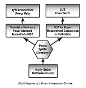
Characterizing RF power sensors is commonly done using a direct comparison system which employs a resistive RF power splitter with a power standard connected to a power meter. One of the most stable and repeatable type of power standards are thermistor type RF power sensors. The thermistor is part of a DC bridge circuit; RF power is determined by changes in DC voltage on the bridge circuit, caused by incident RF energy. The TEGAM/Weinschel Models 1806/1806A utilize this method. While measuring RF power this way is very reliable and well established for use in cal labs, it can be a cumbersome task.
Several years ago, Weinschel Corp. employed a method in their power sensor calibration system to make the task more manageable. Instead of measuring changes in the DC voltage, an analog leveling loop was used to set the DC power. This made the task of calibrating RF power sensors simpler and faster because the operator did not need to take and record readings from a voltmeter and then calculate DC substituted power. With an analog leveling loop the operator simply selected the desired test level.
For additional information, please click here
Download full block diagram below
Advertisement

Learn more about Tegam


