Charging Smart Batteries via the SMBus
Control chips provide key features
for implementing
Smart Battery standards
BY ROGER CHEN
Maxim Integrated Products
Sunnyvale, CA
The ever-difficult task of charging a battery has been further complicated by the variety of battery-operated systems and battery chemistries that currently exist in the marketplace. System manufacturers have responded by producing a variety of proprietary charging schemes and–in the case of notebook computers–creating an array of interface software for controlling a computer's power circuitry.
The System Management Bus (SMBus) specification is a key element in alleviating this confusion. The standard specifies communications between various elements of a battery-charging system over an I2 C data bus and is among the documents cited in the Advanced Configuration and Power Interface Specification (ACPI). A collaborative effort by Intel, Toshiba, and Microsoft, ACPI standardizes the interface between a computer's host controller and its power circuitry. ACPI also cites the Smart Battery Charger and Smart Battery Selector specifications, which define interfaces to the battery and charger.
The SMBus and Smart Battery specifications outline the requirements for a standard “Smart Battery” system that supports multiple battery types with chemistry-independent charging (see below , “Where to find the SMBus specs”). However, these documents neglect many important details and constraints that apply in an actual system. For the designer, an appreciation of such details can ease the transition from block diagram to finished design, while improving the component selection process.
Component manufacturers have simplified this process by offering products tailored to the needs of SMBus applications. These parts, which range from specialized connectors to highly integrated charging chips, address a number of electrical concerns not addressed in the standards.
On the mechanical side, the choice of a battery connector can determine whether a battery is damaged during installation. Within the actual circuitry, control ICs can prevent damage to power circuits, reduce unnecessary drain on the battery, and maintain the integrity of SMBus data.
Ground-pin-length problems
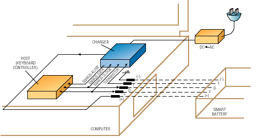
The Smart Battery Charger specification states that the battery's presence should be detected by monitoring resistance at the Smart Battery connector's thermistor or T pin (see Fig. 1 ). According to the standard, a Smart Battery Charger contains a ChargerStatus register, which stores information relating the presence of the battery in the system (indicated by the Battery_Present field) to the condition of the battery's thermistor (indicated by the Thermistor_Or and Thermistor_Hot fields). In general, if the thermistor's resistance measures less than 100 kilohm (such that Thermistor_Or is set), then a battery is installed as indicated by the setting of the Bat-tery_Present bit.

Fig. 1. The SMBus, Smart Battery Charger, and Smart Battery Selector
specifications outline the basic requirements for a battery-charging system
that supports multiple battery chemistries.
The Smart Battery's thermistor also serves as part of a fail-safe mechanism that prevents battery charging in the event of failure in the digital communications. If the battery pack overheats and the thermistor's resistance falls below 3 kilohm (indicated by the Thermistor_Hot condition), the charger must shut off. It must not only shut off, but remain off when the condition is removed. Otherwise, temperature will oscillate around the Thermistor_Hot threshold and overheat the battery.
The Thermistor_Hot function can be a source of difficulty when using standardized Smart Battery connectors such as those offered by AMP (Harrisburg, PA). On the AMP connector, all contacts have the same length, which allows either the positive or negative terminals to make contact first during battery installation.
If the Smart Battery positive terminal makes contact with the computer positive before the negative terminals connect, then the data, clock, and thermistor signal lines (on the computer side) all become negative with respect to the computer ground. That situation corrupts the computer's SMBus and sends a false Thermistor_Hot signal to the charger.
The premature contact of positive terminals can also destroy chips. The computer's clock (C) and data (D) terminals have diode clamps to ground, as do all CMOS open-drain terminals. By preventing the computer's C and D terminals from going negative, these clamps short the battery's C and D terminals to its positive terminal, thereby destroying the Smart Battery's logic circuits.
A simple solution is to lengthen the header's negative contact. This fix is currently being implemented by AMP, which at the time of this writing has two preliminary drawings (part numbers 96-2197-7 and 96-2197-8) for a standard Smart Battery connector with the longer ground pin.
Protecting the signal lines
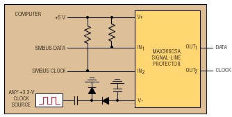
If a faulty Smart Battery shorts its clock, data, or thermistor terminal to its positive terminal, the raw battery voltage can destroy unprotected ICs in the computer's SMBus host and Smart Battery Charger subsystems. Figure 2 illustrates one approach to fault protection.

Fig. 2. Maxim's MAX366 protects circuitry in the computer's SMBus host
and Smart Battery Charger subsystems against shorting of the battery's
signal lines and positive terminal.
In this circuit, a three-channel signal-line protector (Maxim's MAX366) prevents current flow when signal-line voltages exceed the supply rail. The device guards against fault voltages as high as ±30 V, while consuming less than 1 µA of supply current. The resistance from input to output is typically less than 100 ohm.
Detecting the battery
Within the smart charger, the ChargerStatus register contains fields that indicate whether the battery and battery-charging voltage are present. To detect the battery, the T terminal must be pulled to a reference voltage.
This implies that the charger and reference voltage must take power from the battery even when the charging voltage is absent. The result is wasted power, because the charger and the Smart Battery thermistor are used only during charging. They need not be active when the system is operating on battery power.
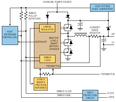
A Smart Battery Charger circuit, such as Maxim's MAX1647, can address this problem (see Fig. 3 ). The MAX1647 is a step-down switching controller with D/A converters that digitally set the regulation points. To comply with the Smart Battery Charger specification as a Level 2 charger, it also includes control logic and an SMBus serial interface.

Fig. 3. Taking its power from the charging power source, the MAX1647
charger IC performs battery detection without draining the battery.
The charger chip does not load the battery because it takes power from the charging power source. When the source is removed, the MAX1647 cannot respond to SMBus requests.
If the host is alive and the charger IC does not respond, the battery must be present (otherwise, the host has no power). If the charging power source is connected, the charger will acknowledge its own address whether the battery is present or not.
Turning off battery broadcasts
In the Smart Battery system envisioned by Intel and Duracell, the battery continuously broadcasts its desired charge current and charge voltage to the charger. To do this, the battery must become the SMBus master–it must control the serial clock and decide when to initiate communications.
This works if no host is present, but the presence of the host (another bus master) complicates the situation. If both initiate communications at the same time, the resulting collisions can disrupt the bus data with unpredictable results.
Another problem with battery-broadcast messages is that they go not only to the charger as intended, but also to the host. If the host doesn't support slave-mode operation, these messages will go unacknowledged, cluttering the bus with unanswered messages. The keyboard controller in many host computers uses general-purpose I/O pins to bit-bang the SMBus in software, which virtually excludes slave-mode operation.
A solution is to detect when the battery is inserted and immediately instruct the battery not to broadcast messages. Devices such as the MAX1647 can perform this operation.
Where to find the SMBus specs
Further information about the standards referred to in this article can be obtained from the World Wide Web. The Advanced Configuration and Power Interface Specification Revision 1.0 is available at http://www.teleport.com/~acpi. The System Management Bus, Smart Battery Charger, and Smart Battery Selector specifications are available at http://www.sbs-forum.org. For more information about AMP's Smart Battery connectors, contact Larry Freeland at 717-780-6045.
Advertisement


