Here are solutions to the problems you may encounter
BY KORY SCHROEDER
Director of Marketing and Engineering
Stackpole Electronics
www.seielect.com
Many factors affect the long-term reliability of ceramic-substrate-based chip resistors. Among those are changes in resistance due to soldering, temperature changes, or even the expected shifts in resistance over the lifetime of a part during normal operating conditions.
Seen and unseen cracks
One often-overlooked factor that affects 2010 and 2512 size ceramic substrate-based chip resistors, both thick and thin film, is the potential for parts cracking or for solder-joint failure. Careful analysis of application conditions and proper PCB design greatly reduce the occurrence of this failure, but in some cases chip resistors built on ceramic substrates are simply not suitable.

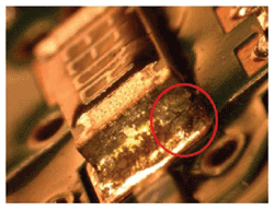
Fig. 1: A 2512 size chip resistor showing cracking at the solder joint.
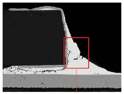
For occurrences such as those seen in Fig. 1 , detecting the crack in the solder joint is relatively straightforward. Often, however, the cracks are not easily visible. They may be too small to be seen under normal magnification, or may be on the bottom of the part or termination. However, there are some warning signs that may indicate the problems exist.

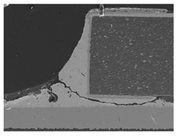
Fig. 2: 2512 size chip resistor cracked solder joint cross section.
Typically, a chip resistor with a solder joint or component microcrack will exhibit an unusually high shift in resistance after the mechanical, thermal, or electrical stress that caused the crack to develop. Standard general-purpose resistors should shift less than 1% from their initial value once all manufacturing operations are complete. Resistance shifts between 1% and 3% would be suspect and any shift of more than 3% after manufacturing should definitely be investigated for cracking. In this case, the cracks are almost always seen at or near the end termination, but may not be visible on the surface of the part or termination.
Improper placement force
It should be noted that another major cause for cracked ceramic chip components is improper placement force. MLCC capacitors regularly experience this problem since the height of the component can vary widely from one manufacturer to another.
For chip resistors, it is less common to have cracks that are due to variations in component height; chip resistor substrates are fairly close in thickness for all major manufacturers. However, if pick-and-place machines aren’t properly maintained and calibrated, or if the placement speed is at the upper end of equipment capability, it is possible to experience cracks due to the machine exerting too much force. This typically causes a crack in the component from one side of the part horizontally to the other, always near the middle of the part and usually in a relatively straight line.
The cracks will often originate at the bottom of the part and propagate to the top. In some cases, the crack may not extend through the film resistive element, in which case the part may still read within tolerance. The part will certainly open if there are any mechanical or thermal stresses to which the circuit is exposed. This would cause a latent failure that would be very difficult to detect before the end product reaches the field.
Material expansion
Cracks due to material expansion differences normally present themselves at or near the termination and usually are much less linear. The real cause of this type of failure is the difference in coefficient of expansion between the PCB and the ceramic chip resistor. Stated simply, the PCB can expand, contract, and flex significantly while the ceramic chip can’t. While differences in coefficient of thermal expansion between the two materials are certainly part of this, it is still possible to have this type of failure under conditions with no significant thermal gradients.
Solutions
Components can be exposed to bending and flexing forces from the PCB due to screw mounting, connectors being attached and unattached, or from vibration. For end products where the PCB is mounted into the unit using screws, or when connectors that need to be plugged and unplugged are present, one possible solution is to move all 2010 and larger case size chip components as far away from the connector or mounting hole as possible. For those situations where this isn’t feasible, or when the circuit assembly is necessarily subjected to vibration, such as when mounted to a motor for example, another solution must be sought.

Fig. 3: Surface-mount resistor packages with compliant terminations.
For applications that already have some through-hole components and have the board space, the answer can be as simple as switching to a leaded through-hole component. But with the proliferation of surface-mount components and manufacturing processes this isn’t always practical or feasible. It doesn’t make sense to change a resistor from SMT to through-hole if that is one of the only parts on the board that isn’t surface mount. The most popular currently available surface-mount solution to this problem is the molded SMD package with formed metal tab leads that run down the side of the part and under it. These compliant terminations are free to flex back and forth with the board and effectively eliminate cracking or solder joint integrity problems. Molded SMD packages such as this offer a wirewound resistive element usually, but thick film, thin or metal film, and carbon composition elements are also readily available. Wirewound elements are very popular because of their ability to withstand extreme temperatures. Surface mount molded wirewounds are typically rated for operation at temperatures up to 275C, where all other element types are limited to 155C and below.
In addition to molded SMD packages, there are also high power SMD packages where a metal housing is used with the chip resistors mounted to the underside; this configuration also allows the metal terminations to expand and contract freely with the board. These two options, while readily available, are more expensive than the standard thick-film chips they replace. These package types are also fairly large in terms of both board space used and height. In addition, the SMD molded wirewounds are inherently inductive, even when non-inductively wound, and are limited in resistance range to only those resistance values below 5 kΩ.
The rapid development and acceptance of pulse withstanding chip resistors and high-power-rating chip resistors have allowed many applications that had been using through-hole resistors in the past to move to surface-mount devices. This simplifies the manufacturing processes and typically can save a significant amount of board space and product weight. However, some applications are subject to thermal and mechanical stresses, which cause component cracking and solder joint integrity problems. However, with careful analysis of board layout and proper component selection, overall reliability can be greatly improved for resistor power requirements of 0.5 W and higher. Surface mount resistors with compliant metal terminations offer a readily available solution that is completely immune to component cracking and solder joint or termination failure. ■
Advertisement
Learn more about Stackpole Electronics


