Choices for measuring solar-cell output power
Standard, off-the-shelf instrumentation can often serve where turn-key testers are unable to go
BY BOB ZOLLO
Agilent Technologies
Budd Lake, NJ
http://www.agilent.com
In a world dealing with environmental issues and energy shortages, the promise of clean, renewable energy from solar power is driving development of solar-cell technologies. This growth in the solar industry has intensified the need for solar-cell (and solar-module) test and measurement solutions and, as solar-cell size and efficiency grow, cell testing involves managing higher current and power levels, creating the need for more-flexible test equipment.
Off-the-shelf electronic loads can be used to test solar cells when turnkey solutions are not flexible enough. When configured and applied properly, loads can be used to make all power-related measurements on the output of the solar cell or solar module.
Several key parameters are typically measured on solar cells. These parameters are:
• VOC — Open-circuit voltage. The cell voltage at which point there is zero current flow.
• ISC — Short-circuit current. The current flowing out of the cell when the load resistance is zero.
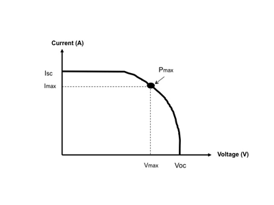
• Pmax — Maximum power output of the cell. The voltage and current point where the cell is generating its maximum power. The Pmax point on an I-V curve (Fig. 1 ) is often referred to as the maximum power point (MPP).
• Vmax — The cell’s voltage level at Pmax.
• Imax — The cell’s current level at Pmax.
• η — Conversion efficiency of the device. The percentage of power converted (from absorbed light to electrical energy) and collected when a solar cell is connected to an electrical circuit. This term is calculated by dividing Pmax by the input light irradiance (E , in W/m², measured under standard test conditions) multiplied by the surface area of the solar cell (AC , in m2 ).
• Fill factor (FF) — Pmax divided by the VOC times ISC.
• Cell diode properties.
• Cell series resistance.
• Cell shunt resistance (or parallel resistance).

Fig. 1. This I-V curve for a solar cell shows Pmax and its relation to Imax and Vmax .
Common solutions
Today, solar-cell test solutions come in two main forms: complete turnkey systems and general-purpose test instruments. Complete turnkey systems work well for validation and manufacturing, where these systems ensure test repeatability, as they are programmed to perform a specific battery of tests on the solar cell.
Researchers will often turn to general-purpose test instruments found in semiconductor design labs. Researchers use semiconductor device parameter analyzers for measuring diode device characteristics and LCR meters for measuring material/device inductance, capacitance, and resistance.
When testing at full solar-cell output power is needed, many research labs will have low-power four-quadrant power supplies (sometimes called an SMU) that can:
• Accurately source positive and negative voltages. (Sourcing is also called forcing.)
• Accurately source positive and negative currents. (Sourcing negative current is also known as sinking current into the supply.)
• Accurately measure the voltage and current at the DUT. (Measuring is also called sensing.)
While these four-quadrant supplies are highly versatile, they are limited in range of maximum current and power that can be delivered to the DUT. Most accurate four-quadrant supplies are limited to 3-A or 20-W continuous power.
This maximum current and power may be acceptable for testing smaller individual cells, but as cell technology pushes for higher efficiency, higher current density, and larger cell sizes, the power output could quickly exceed the maximum ratings of these four-quadrant supplies. Solar modules often exceed 50-W output and can climb as high as 300 W or more, meaning many of the tests on modules can’t be done with a four-quadrant supply.
In these cases, engineers should turn to standard off-the-shelf electronic loads, dc power supplies, DMMs, and data acquisition equipment including temperature measurement, scanning, switching, and data logging for the flexibility they need to conduct unique tests over a wide operating range and with the desired measurement accuracy. For example, one can use a data acquisition system to scan ambient and DUT temperature, the voltage of a calibrated reference cell, and various other test parameters that need to be captured during the test.
Testing outdoors
Some engineers will run tests using turnkey solar-cell testers that employ a solar simulator, which is a standardized light source that lets them control the light energy into the solar cell. However, when the solar cells or modules are very large, solar simulators cannot produce adequate light.
For example, the solar module being tested might be part of large outdoor solar-collection system. In this case, the sun itself would be the only practical light source for the test. Since it is not practical to transport a full turnkey tester sans solar simulator outdoors, this test would need to be performed with some other test solution built up from standard test instruments.
Another consideration when testing outdoors is temperature. Since cell performance is impacted by temperature, it will be necessary to monitor temperature during test. Not only is cell performance temperature dependent, but so is the performance of the test equipment.
Many instrument vendors do not specify the performance of their test equipment outside a narrow range near room temperature, such as 25 ± 5C. Others provide a temperature coefficient spec, which allows you to adjust the accuracy specifications of the test equipment to correct for operation in temperatures outside its specified operating range.
Loads for higher power test
For higher power applications, a standard electronic load can be used to test solar cells. Many engineers will not think of an electronic load for testing solar cells, as they are accustomed to either turnkey systems or four-quadrant supplies.
Given that a solar cell produces energy, when it is tested with a four-quadrant supply, the supply is actually operating in a mode where it has a positive voltage being forced by the solar cell onto the supply’s terminals. At the same time, current is flowing from the solar cell into the four-quadrant supply’s terminals, meaning the four-quadrant supply is seeing negative current (with respect to its terminals). Under these conditions, it is also correct to say that the four-quadrant supply is sinking current.
Electrically speaking, an instrument having positive voltage forced onto its terminals and current flowing into itself (that is, sinking current) is called an electronic load. Therefore, for most solar-cell tests where light is shining on the solar cell and the solar cell is generating power, the four-quadrant supply is actually acting like an electronic load.
The advantage to using an electronic load is that loads are available in all current and power levels. The limitation of 3 A, 20 W imposed by the four-quadrant supply is easily overcome using electronic loads rated at 50 W and higher up to thousands of watts and hundreds of amperes.
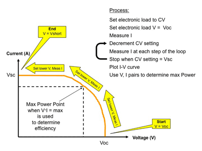
Electronic loads can operate in constant voltage, or CV, mode. In CV mode, the load will adjust the current flow through the itself to regulate voltage across its terminals to hold a constant voltage value. Thus, CV mode can be used to create a voltage sweep, where you use the load to control the voltage across the output of the solar cell and then measure the resultant current flow (see Fig. 2 ).
Some loads (such as the Agilent N3300 series) can quickly execute a list of CV setpoints to sweep the output voltage in CV mode, thus quickly tracing the I-V curve. At the same time, the load can digitize the current waveform that flows out of the solar cell into the load, similar to capturing a scope trace.
By plotting the swept-controlled CV voltage vs. the digitized actual current, you can create an I-V curve. And because this is done as a fast sweep, the whole test can be conducted in approximately 1 s before the cell heats up and changes temperature due to heating effects of intense light sources.

Fig. 2. A solar cell’s I-V curve can be measured using an electronic load in CV mode.
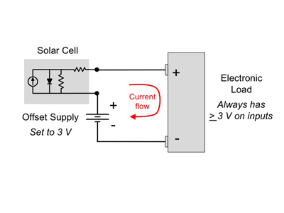
Many electronic loads, though, have a low-voltage operating limitation that requires a minimum operating voltage across the load’s positive and negative input terminals. The minimum input voltage for a typical electronic load is 2 to 3 V. To overcome this limitation, a dc power supply can be put in series with the load (see Fig. 3 ). This dc power supply is called an offset supply, as it provides an offset voltage to the load.

Fig. 3. An electronic load can be configured for solar-cell testing using a dc offset supply.
Typically, the offset supply is set to 3 V to ensure that the load’s minimum voltage requirement is always met. The voltage from dc source will have no impact on the solar cell, which is a floating device; it merely biases the solar cell up by 3 V. For more information, Agilent Technologies offers application note Solar Cell and Module Testing , publication number 5990-3262EN. ■
Advertisement
Learn more about Agilent Technologies


