As applications for these devices expand, design challenges change
BY TAMARA SCHMITZ
Intersil, Milpitas, CA
www.intersil.com
Proximity sensors, which are designed to detect the presence of nearby objects without any physical contact, have evolved from narrow application in industrial automation systems into broad use. They can now be found in consumer and communications products ranging from ATM and vending machines to security systems to leading-edge personal computers. Proximity sensors are used in the most advanced mobile handsets to disable screens when a user is on a call, preventing accidental hang-up or muting.
But applying proximity sensors in these new applications is no longer simply an electrical challenge. Using them requires mechanical expertise as well as experience in optical system design, in which engineers must combine light sources with sensors that effectively detect the light.
This article will briefly review some of the most interesting and innovative applications for proximity sensors, describe some of the important criteria for selecting the best sensor, and explain how designers must combine electrical, mechanical, and optical skills to complete a successful design.
Proximity sensor 101
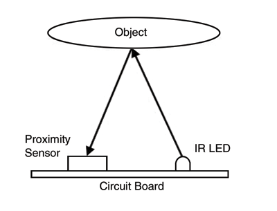
Most electronic components accept an electronic signal and provide an electronic output. On the other hand, a proximity sensor works in tandem with an infrared (IR) LED. The sensor commonly provides the signal to drive the IR LED and then waits to measure any reflected infrared signal off of a nearby object. The time delay between send/receive and the brightness of the received signal can be measured to discover the distance of an object from the proximity sensor.
This setup clearly requires optical considerations. Is there a lens over the proximity sensor? Is there anything, like the dark glass on a cell phone face, for example, that can hinder the reception of light? Is there any scattering or leakage from the emitting IR LED that makes it to the receiver and tricks it into believing there is an object nearby?
It’s a big enough challenge that a proximity sensor needs circuit designers to mold the electronics and optics experts to guarantee clear reception. There is even one more critical need. The mechanical design placing the components of a proximity sensor system is critical. The most obvious choice is the placement of the IR LED and the proximity sensor. In an ideal world, they would be placed in exactly the same spot. That way, the receive signal would come at the same angle from which it was transmitted. Any roughness in the texture of a reflective surface would have less effect in this direct approach.

Fig. 1. The basic setup of a proximity sensor system.
Unfortunately, the laws of physics don’t allow the transmit IR LED and the receive sensor to occupy the same space on the board or in the package. Therefore, they are placed side by side, as shown in Fig. 1 . How close should they be placed? Since we had hoped they could be in the same place, we would probably want to place them as close together as possible. Are there any issues that limit how close we can put them together? Actually, there are. LEDs aren’t perfect pinpoint light sources. To be honest, we’d be better off with a laser, but that is too expensive. Instead of a small beam of light, we get the somewhat diffused beam of an LED. While most of the light is transmitted directly above the LED, some of it escapes to the sides. It is this side transmission that can cause false triggers in the receiver.
In the example developed here, the receiver is optimized to measure a certain amount of light. The amount of light will be related to the distance of the object from the system. If an object is close, more light will be reflected back to the sensor. If an object is far, less of the light is reflected back to the sensor. That could help explain why the first proximity sensors in the market are designed for signaling when an object is centimeters from the sensor. This is a convenient distance to allow a cell phone to know when the user has brought the device near his or her face to talk on the phone. The addition of a proximity sensor allows the phone to turn off the screen during this time, saving power and prolonging battery life.
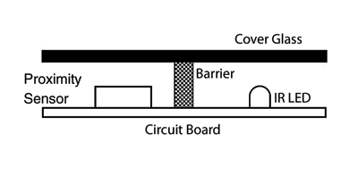
Still, we are deciding how close to place the IR LED to the receiving sensor. The answer is “as close as possible so that you don’t cause false triggers.” One solution is to add another structure. The designer might place a small barrier or wall between the IR LED and the sensor. It would be best if this barrier was as tall as possible. In the cell phone example, there is typically a certain distance available between the circuit board and the cover glass. That would limit the size of the barrier that could be used. As long as the barrier is made of something that light cannot permeate, the other dimensions of the barrier can be set by ease of use or cost of material, as illustrated in Fig. 2 .

Fig. 2. The use of a barrier in a proximity sensor system to avoid signals bleeding from the IR LED directly into the receiver.
Another option to improve signal quality is the use of a lightpipe. A lightpipe is a small cylinder of plastic placed above the sensor to channel light from the glass directly into it. Remember, while the barrier can be the same height as the space between the cover glass and the circuit board, the sensor will not be as tall.
Light coming through the cover glass might bend at the glass-air barrier and travel at an angle into the phone instead of into the sensor. A lightpipe fills the space between the sensor and the cover glass, theoretically optimizing the amount of light that reaches the sensor.
Tricky business
Hopefully it is clear that knowledge of mechanical engineering and optical knowledge must accompany the electrical design that predominates in devices like cell phones. Simulating these systems is equally tricky, taking into account the optical properties and physical locations of all of the materials involved.
In addition, most cell phone companies want their devices to be simple to use. For example, they don’t want to calibrate the proximity system for users with different skin or hair colors. Interested designers will check datasheets, so here is one example graph from a popular combination ambient light/proximity sensor part, the ISL29028. Figure 3 shows how two reflective surfaces affect distance readings.
facn_intersil03_nov2010 Fig. 3. ISL29028 proximity sensor reading vs distance for a 10 x 10-cm reflective card.
The use of proximity sensors goes beyond cell phones. A customer once told me that if we built a proximity sensor that reliably worked in the range of 10 m, he would put them on the tips of every plane he used to avoid bumping the door on the way out of the hangar. Proximity sensors have been used as burglar devices where an ambient light sensor or trip wire could be fooled. Robotics students at universities are using them to give devices the ability to react to approaching people or when they near an obstacle. The truth is that proximity sensors are just beginning to reach their strides. New uses are being discovered all the time. The popularity of these new uses will determine whether proximity sensors of the future will strive for distance, resolution, lower power, or something totally new. ■
Advertisement
Learn more about Intersil


