Choosing a scope for serial-protocol test: Five criteria
Selecting the right oscilloscope need not be as complex as it is critical for successful chip development or board inter-operation
BY WILLIAM DRIVER
Product Manager
LeCroy
www.lecroy.com
With all the varieties and speeds of serial data communication protocols in use in so many devices and between so many different chips, choosing the right oscilloscope can be as complex as it is critical for successful chip development or board inter-operation. Each protocol or bus standard has unique physical- and protocol-layer requirements, as defined by the industry organization that is chartered with developing and maintaining the specification. Many oscilloscopes are designed to address the exact specifications of particular protocols and can serve as protocol “experts” for development engineers.
Some of the attributes that should be taken into consideration while choosing an oscilloscope for a project that deals with serial communication protocols are: bandwidth and sample rate, compliance packages, decode packages, debug toolset, and analysis toolset.
Bandwidth and sample rate
Bandwidth and sample rate are the paramount specifications for choosing any oscilloscope. When making protocol related measurements, an oscilloscope must have enough bandwidth to properly resolve the fastest bit rate.
Although there are exceptions, an oscilloscope’s bandwidth should usually be at least five times higher than the system’s fastest digital clock rate. The five-times rule allows the scope to capture the critical fifth harmonic needed to display the signal’s proper shape. (Some specifications require meeting a minimum rise- and fall-time or other requirements in addition to bandwidth.) A few popular protocol standards, their bit rates, and the corresponding bandwidths to illustrate their relationship are shown in the accompanying table
Serial protocol standard rates and recommended bandwidths
An oscilloscope’s sample rate for a particular protocol should generally be twice the scope’s bandwidth to ensure that the signal is properly sampled according to the Nyquist sampling theorem. However, you need 5 or 10 times the sample rate to ensure proper viewing of measurements.
Compliance packages
Compliance testing shows how well your device meets a specification’s defined physical- and protocol-layer requirements. Compliance tests, some of which are automated, are written for specific protocol standards, and are available with certain oscilloscopes. Automated testing includes automated scripts, connection diagrams, and test reports that can simplify the compliance process while shortening product development time.
Few devices work perfectly the first time and initial tests often reveal compliance failures. An oscilloscope with a wide variety of serial-data tools can help diagnose and resolve these problems.
Decode packages
Since it is possible to pass the physical compliance tests but fail the protocol compliance tests, it is crucial to be able to view both the physical and data-link (protocol) layers, preferably at the same time.
Some oscilloscopes use advance algorithms to deconstruct a waveform and reveal the embedded protocol. Developers can then simultaneously view an application layer’s header, address, and data information overlaid on the waveform.
Decoding a protocol with table view and search features is a critical aid in debugging a serial protocol. Troubleshooting the full handshake sequence in a protocol such as PCI Express (PCIe) may require capturing hundreds of packets.
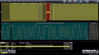
Table functions in the oscilloscope can display and organize multiple decoded packets and make it easy to find specific packets of interest. Touching a specific packet on the screen should enable you to zoom right to an area of interest on the waveform (see Fig. 1 ). The ability to search for individual packets with specific data values greatly eases the task of searching through hundreds of individual address, data, or primitive bits.

Fig. 1: A decode of a PCI Express Gen 1 acquisition shows a zoom of a DLLP packet. The highlighted row in the table correlates with the zoom view.
Debug toolset
Decode features help to visually understand a serial data stream and identify a potential problem, but isolating a problem requires additional tools that provide deeper insight into hard-to-solve serial data problems.
True hardware protocol triggers can completely isolate specific message events. For example, an 80-bit serial trigger could be used for data signals up to 3 Gbits/s. This would include high-speed protocols used in storage and peripheral interconnects such as SATA, PCIe, and USB 3.0. A conditional hardware trigger is very useful for lower-speed protocols found in embedded, automotive, avionics, and military products (for example, I2 C, SPI, UART, CAN, LIN, FlexRay, I2 S, and MIL-STD-1553) to trigger on data and/or address ranges greater than a particular value.
An advanced serial debug toolkit option can quickly and easily characterize a serial data system’s timing and bus measurements. Automated timing measurements are useful for determining cause-effect validation, such as the time difference between two packets.
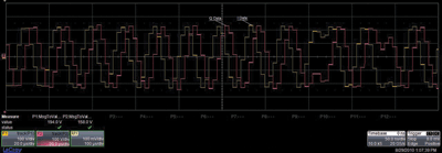
Timing relationship measurements are critical in successfully characterizing the load on a bus, but the ability to extract the analog data from each packet can be equally effective. Graphing analog data values over a long acquisition record can represent a true analog conversion, thus helping to identify issues in the protocol system. This can be useful when viewing temperature sensor data or the I and Q sent from a DigRF 3G or v4 MIPI signal (see Fig. 2 ).

Fig. 2: PROTObus MAG Serial Debug Toolkit on a LeCroy oscilloscope showing MIPI DigRF 3G I and Q analog waveforms converted from digital data payload fields.
Analysis toolset
When analyzing a problem, you need to go beyond compliance testing and actually break down the physical layer into views that can help show the actual causes of a failure. Advanced eye diagrams and jitter tests are invaluable because they offer different ways to gain deeper insight into your problem.
By using its full memory, a good oscilloscope should be able create high-resolution eye diagrams to analyze a signal’s maximum statistical significance. A related tool, such as LeCroy’s IsoBER, that displays amplitude variations and extrapolates the results of increasing bit-error rates can quickly determine the minimum eye opening and detect crosstalk by analyzing vertical eye closure. These measurements are not possible with standard eye diagram techniques.
Many protocol standards require jitter testing. An oscilloscope with integrated clock and data jitter breakdown tools is very useful in testing most communications links, especially the higher bit-rate protocols such as USB 3.0, PCIe, and SATA. These integrated tools use advanced jitter decomposition methodologies and tools to simplify analyses of jitter components (such as TJ, RjBUj, and DDj), thus providing more information about the basic causes of jitter.
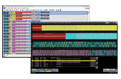
Protocol analysis is a powerful tool for solving serial data problems, but every oscilloscope does not offer simultaneous protocol analysis displays. An oscilloscope that features a time-correlated data-link layer view in a simultaneous display can quickly reveal key relationships between analog trace- and protocol-level behaviors (see Fig. 3 ). This is particularly useful with protocols that start with a negotiation of speed or a handshake, where many failures first occur.

Fig. 3: LeCroy’s ProtoSync option combines the physical layer view with a simultaneous view of data link layer decodes. This example shows both views of a PCI Express Gen 1 DLLP packet.
Whether the protocol under test is a new emerging standard requiring jitter and eye diagram testing, a mature standard requiring only compliance testing and device debugging, or an embedded standard requiring protocol, measurement, and timing analysis, modern oscilloscopes offer a variety of communication protocol testing options to speed up your test and measurement process. With one of these “experts” on your test bench, you can work faster and more efficiently. ■

Advertisement
Learn more about Teledyne Lecroy


