Choosing inductive components for high-speed interconnects
For next generation networks, new magnetic technologies offer improved performance, higher quality, and automated production
BY STEVEN R. KUBES
Sr. Product Manager, 10G and PlanarMag Product Technology
TE Connectivity
www.te.com/planarmag
Impedance matching and filtering of high-speed Ethernet data is commonly performed using hand-wound toroidal coil transformers and chokes. These devices are relatively bulky compared with other modern components, and so must typically be mounted on the pc boards adjacent to the RJ-45 connector. Some innovative designs integrate a small pc board (PCB) with hand-wound transformers into the base of the RJ-45 connector to provide a fully-filtered Ethernet jack. And in applications where ganged ports are required, it is common to find these magnetic components incorporated into a back-plane PCB.
However, all of these implantations have one element in common – multiple hand-wound toroidal coils. For such hand-wound coils, the ability to predict performance and yield becomes increasingly difficult, especially at frequencies of 1 GHz or higher. The continued use of hand-wound coils at higher frequencies will mean more errors, more production rejects, lower yields, and, consequently, higher prices. In addition, the amount of labor content will increase as well — further increasing costs.
Hand-wound coils will undoubtedly remain popular for lower-frequency interconnects and in lower volume applications. Today, magnetic windings are predominantly manufactured by hand in factories in China. With about 100,000 people winding these coils, manufacturing consistency varies depending on the expertise of the workers, and turnover can be as high as 50%.
When downturns and the resulting layoffs occur, even experienced workers can be eliminated. Once the market improves, it can take several months to train and develop a new workforce and reestablish supply continuity.
Such a work-force situation can obviously lead to extensive product supply shortages and quality issues. As the demand for Ethernet ports continues to increase, and more and more of these ports support 1-Gbit or even 10-Gbit data rates, the data communications industry is looking for alternatives to wound coils.
Magnetics in the substrate
One alternative can be found in advanced magnetic technology. By leveraging the latest 3-D PCB processes, this technology allow manufacture of wide-band planar transformers and common-mode chokes embedded in a substrate. Well-established PCB techniques are used to more efficiently manufacture reliable, consistent structures.
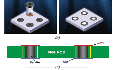
The process starts by drilling controlled-depth holes in FR4 PCB and inserting ferrite cores [Figure 1(a) ]. Then an epoxy polymer is applied that fills the cavities as well as surrounding and protecting the ferrite. The special epoxy has characteristics that allow manufacturing processes similar to FR4 for panelization, drilling, and vias to create the PCB two-layer process.
After the epoxy polymer is cured, a planarization process ensures a very flat structure. Next two prepreg treatments are performed at elevated temperature and pressure to allow copper to adhere to the FR4.

Fig. 1: Once the PCB is drilled, ferrite cores are inserted and an epoxy polymers is applied (a) Standard drilling forms the vias that go on the inside and outside of the ferrites to form windings once both sides of the PCB are metallized, etched, and soldered. A special technique for creating differential toroidal pairs is part of a wide-band planar transformer patent.
Copper is then applied to both top and the bottom to create a two-layer board and the assembly is etched, after which it goes through a solder mask process that fills in the vias and deposits the solder mask on top [Figure 1(b) ].
A thin tape layer is applied to one side of the PCB and it then sawn on the opposite side and singulated into individual components, in much the same way as in a semiconductor process (Figure 2 ). Then testing is performed on each device similar to the 100% testing techniques used for semiconductors to verify conformance to critical parameters and the consistency of the manufacturing process.

Fig. 2: High-volume PCB technology combined with proprietary manufacturing techniques has lead to a highly precise planar magnetic device that is mass produced and cut into die-like units as indicated here.
PCB-based technology using precision photolithography allows the manufacturing of boards containing hundreds and even thousands of planar magnetic devices.
Device performance
The planar magnetics advantage is complete control over leakage inductance, capacitance, and the shapes of the petals, or wrappings. The consistency of the manufacturing process is based on design rules for controlling the size of the component.
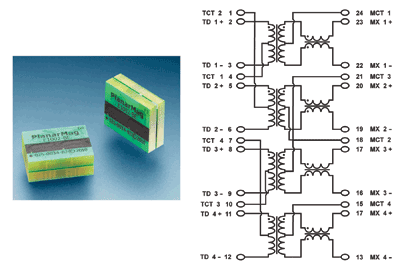
For a 1-Gbit BASE-T Ethernet media filter and isolation transformer with a 1:1 turns ratio (Figure 3 ), the tolerance is ±2% at 100 kHz.

Fig. 3: The 1-GbitHz planar magnetic 1-Gbit Ethernet media filters shown here embody the schematic at right.
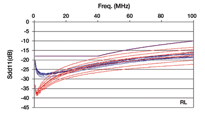
Because of the controllability in the manufacturing of the embedded planar magnetics, device-to-device performance is more consistent than possible with hand-wound coils. Since the embedded magnetic product structure performs as a tightly-controlled narrow pass filter with a high degree of consistency and repeatability, the Bob Smith termination commonly used for impedance matching can be eliminated or the components reduced in many applications. In general, design margins can be reduced compared to wound coil designs (see Figure 4) .

Fig.4: The cable-side differential return loss of connectors utilizing embedded magnetic product technology (blue) is demonstrably more repeatable than that of equivalent connectors with hand-wound coils (red).
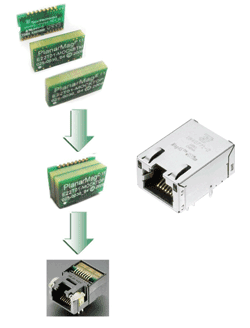
A fully integrated connector utilizing the embedded magnetic product technology (Figure 5 ) targets applications that require reduced height and small form factor footprint, such as laptop and notebook computers.

Fig.5: Use of embedded planar magnetic technology results in a simpler integrated connector module (ICM).
Magnetic components are an essential aspect of high-speed data communications interfaces. As data rates continue to increase, the design and production limitations of hand wound coils are becoming more evident. As shown in the table below, evaluation of three key design criteria can provide guidance on whether to consider hand-wound ferrite coils or embedded planer magnetic product technology.
A white paper that provides more information about the new PlanerMag product technology is available for download at www.te.com/planarmag. ■
| Coil selection criteria | ||
| Criterium | Hand-wound coils | Embedded planar magnetics |
| Data Rates | 10/100 Mbit; 1Gbit | 1Gbit; 10 Gbit |
| Volume | Low to medium | Medium to high |
| Quality/repeatability | Low to medium | High |
Advertisement
Learn more about TE Connectivity


