Not only can measurement accuracy be harmed by high voltages in circuits under test, but so can instruments and people
BY YEO SIOK BEEN
Avago Technologies
San Jose, CA
http://www.avagotech.com/
In high-accuracy data acquisition, it’s a challenge to measure small signal variation when high common-mode voltages (wanted or unwanted) are interfering with the system. These high voltages may exist due to different potentials in two grounds, or sudden, transient overvoltages caused by lightning strikes or power surges from motors or switching devices.
Isolator benefits
Such high voltages can not only impact measurement accuracy, but also damage the test systems and pose a threat to human operators. Thus isolators are needed to physically and electrically separate the tester and operator from the system or device under test.
Isolators provide a higher common-mode voltage range that appears simultaneously between both signal leads and a common ground. In addition, isolators can break ground loopsunwanted currents between two points that share a common ground path; common ground paths are often found in probing system measuring differential voltages.
Because isolators used in measurement equipment are also important for protecting human beings, they are governed by safety standards that cover the design of high-voltage instruments. The main safety standard affecting test-and-measurement instruments today is IEC 61010-1. In this standard, 30 Vrms, 42.2 V peak, and 60 Vdc are considered dangerous voltage levels.
Insulation ratings
IEC 61010-1 categorizes isolators according to four categories of insulation: functional, basic, double, and reinforced.
Functional isolation provides ground-loop-breaking functionality with minimum protection; it does not provide protection against electrical shock. Basic insulation provides only a single level of insulation and does not allow the user to access the system without risk, should the insulation fail.
To provide greater protection for users against shock, double insulation adds an extra layer of insulation to the basic insulation. Reinforced insulation has a single insulation that provides electrical-shock protection equivalent to double insulation, while ensuring a fail-safe mode that automatically leaves system processes and components in a secure state when a system failure is detected and thus allows safe user accessibility.
Beside the insulation type and the working voltage rating, the standard also specifies the required spacingcreepage and external clearanceof isolators for different types of equipment. The creepage distance is defined as the shortest surface path over a solid dialectic between two galvanically isolated conductors. For, say, a system operating with a peak working voltage of 300 V, a creepage of 3 to 4 mm is required. Similarly, the external clearance distance is the shortest distance through air, or the “line-of-sight” distance, between two galvanically isolated conductors.
Isolator types
Isolators are also grouped by how they transmit a signal of interest. The three main types are magnetic, capacitive and optical. Magnetic-coupling-based isolators using a transformer are generally more power efficient, and are used for very long-distance applications. They are susceptible to magnetic interference and absorb unwanted frequency instead of providing “true” isolation.
Capacitive isolators transmit data across an oxide barrier. However, due to the capacitive nature of the devices, they are subject to high-frequency noise at high operating frequency, with lower transient immunity and lower isolation voltage, especially for a monolithic capacitive isolator.
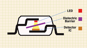
Optical isolators, or optocouplers, usually consist of an LED and a detector with an isolation barrier in between (see Fig. 1 ). The devices translate an electrical signal into an optical one that is transmitted from LED to detector across transparent barrier.

Fig. 1. A cross section of an optocoupler shows how it provides full electrical isolation.
The optical signal is immune to EMI interference and galvanic isolation up to 5 kV is achievable in various package sizes that meet 8-mm creepage/clearance required for a maximum working voltage of 1,414 V peak. Previous limitations in the operating frequency range for optocouplers have recently been overcome and thus the latest devices can transmit signal as high as 50 Mbits/s with propagation delays of only 22 ns.
Optocouplers from Avago provide reinforced insulation and are certified and approved under the IEC/EN/DIN EN 60747-5-2 standard for optically isolated semiconductor components. In addition, common-mode rejection as high as 40 kV/µs is achievable to ensure that high common-mode transients will not impact output logic. Optocouplers are effective in passing the desired differential-mode signals while blocking unwanted common-mode currents and ground offset voltage that can result from ground loop currents.
In-system operation
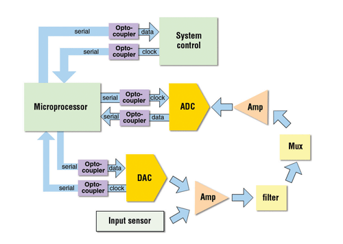
Digital optocouplers can be effectively used in a measurements system’s data acquisition module (see Fig. 2 ). Once the analog signal is sensed, amplified, and converted to a digital signal through an ADC, it is transmitted through a high-speed digital optocoupler before being fed to a microprocessor for measurement processing. By preventing any high common-mode signal or high transient voltage from corrupting the sensed signal, the digital optocoupler increases measurement accuracy.
The information is sent to the system control for any process regulation or information storage activities. Optocouplers are used here to prevent any voltage surge of one module from damaging the other module.

Fig. 2. Digital optocouplers can be used in an instrument’s data acquisition module.
For portable measurement systems, power consumption is often considered key. That’s why more test-and-measurement equipment makers are moving from traditional 5-V to 3.3-V supply voltage designs, and component manufacturers have created isolators like the ACPL-072L that operate with 3.3-V systems.
In the past, optocouplers consumed significant power. However, LED technology has also improved that devices can emit high-brightness signals at lower forward currents. A further breakthrough achieves a higher current transfer ratio, significantly reducing optocoupler current consumption. The HCPL-070A, for example, has a 0.125-mA max average current for a 50% duty-cycle data rate.
Get more information on isolators at http://electronicproducts-com-develop.go-vip.net/testmeasure.asp ■
Advertisement
Learn more about Avago Technologies


