Choosing optical coatings for medical displays
Careful selection of optimal coatings and substrates can result in greatly enhanced display performance
BY JEFF BLAKE and RICHARD PAYNTON
Dontech, Doylestown, PA
http://www.dontech.com
Electronic displays are widely used in the healthcare industry for diverse applications such as patient monitoring, medical imaging diagnostics, archiving medical records, and EMT response. Because display image quality and reliability are critical to both the clinical and diagnostic integrity of patient care, design engineers are challenged to meet a wide range of optical, electrical and mechanical performance standards. Fortunately, various technologies can be used in medical applications to improve ergonomic and regulatory performance of displays and touch screen monitors.
Performance
As defined by the FDA, primary medical displays are used for direct diagnostic interpretation of medical images, as in radiology. Secondary displays are used by medical staff to review patient data. Guidelines established by the American Association of Physicists in Medicine (AAPM) for primary and secondary displays outline the following measurement and performance criteria:
Reflection diffuse (incident light scattered in many directions and ideally lambertian) and specular (mirror-like) reflection.Luminance display brightness expressed in candelas per meter sq. (cd/m2 ) or nits. Typical displays range from 250 to 800 cd/m2 .Contrast ratio expressed as the luminance ratio of the brightest area (typically white) to the darkest (typically “off”). Contrast testing can be inherent (tested in a dark room) or in high ambient light (e.g., 10,000 fc illuminating on the front of the display).Resolution number of distinct pixels displayable vertically and horizontally.Color gamut the displayable color range (plotted on the CIE 1931 chromaticity diagram).Overall visual assessment display performance, including stability and consistency relative to ambient light levels and viewing angles.
In addition, various international standards such as UL60601 (safety of medical devices), UL60950 (ball drop impact resistance) and BSEN-55011 and CISPR 11 (electromagnetic compatibility) often necessitate the modification of commercial off-the-shelf displays to achieve compliance.
Coatings are frequently used in the medical display industry to address a variety of display performance issues (see Table 1 ).
Table 1. Coatings/substrates for enhancement of medical display performance
Coatings can have a direct impact on how the display is perceived. This becomes apparent when we consider that in outdoor and even operating-room environments, ambient lighting levels are very high (up to 100,000 lux) (see Table 2 ).
Table 2. Typical ambient light levels
As a performance characteristic of the display system, readability in high ambient light is dependent upon display luminance, ambient illuminance (light from the environment), and the amount of ambient light that is reflected by the display and its front optical components, such as cover filter or touch screen.
Surface reflections, which occur at interfaces between mediums of differing refractive indices, degrade contrast by reflecting the ambient light. A better understanding of the cumulative effects of surface reflections scan can be attained using the Fresnel equation for normal reflectance, R:
R = [(n1 − n2 )/(n1 + n2 )]2
When the equation is applied for normal incident light to the first surface interface where the initial medium is air (refractive index n1 = 1.0) and the exit medium is glass (n2 = 1.52), the result is a value of 4.25% for the first surface reflection. The high refractive index of transparent conductive coatings used in constructing most resistive touch screens will compound this refection problem, and can increase the reflections up to 8-10% per conductive layer.
Reducing surface reflections
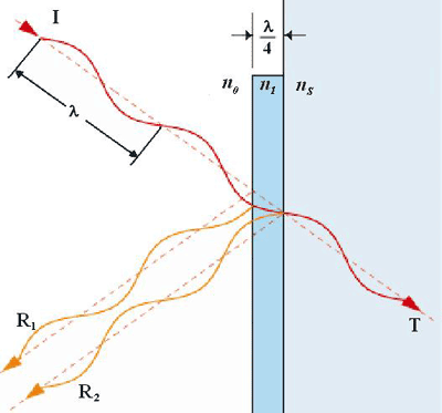
Because surface reflections are the most common cause of contrast degradation in a display system, antireflective and antiglare coatings are commonly used to improve reflection characteristics and performance. Antireflective (AR) coatings are thin-film optical coatings that modify the phase of incident light such that the reflections destructively interfere with one another (see Fig. 1 ) while the transmitting light constructively interferes, thereby increasing the total luminous transmittance.

Fig. 1. Graphical representation of how a simple, single-layer AR coating (λ/4 optical thickness) with low, 1.38 refractive index creates destructive interference.
Application of AR coatings to the front and rear surface of a display filter or touch screen can reduce surface photopic reflections by over 4% per uncoated surface. Antiglare coatings reduce the coherence of the reflected image by scattering spectrally reflecting light and defocusing the reflected image. This lowers the eye’s sensitivity to the reflected images. The scattering/diffusing level of an antiglare coating is expressed in gloss units per ASTM-523.
Hard coatings (antiglare or gloss) improve the mechanical and chemical durability of exposed surfaces so that the optics will comply with the recommended MHRA (Medicines and Healthcare products Regulatory Agency) medical “wash-down” requirements for equipment decontamination. Hydrophobic or oleophobic coatings (fluorocarbon or silane based) are used to minimize fingerprints of the outer surfaces of touch screens and AR coatings. Antimicrobial loaded hard coatings, composed of polymers which release silver ions to inhibit bacterial proliferation, are becoming popular feature of optics used in medical display and touch screen applications.
Optically coupling the rear surface of a touch screen or optical filter with the front surface of the display using an index match bonding adhesive is becoming an increasingly popular method to improve high ambient light readability as it eliminates the reflections between the display and the rear surface of any optics in front of the display, such as a touch screen, while improving the mechanical durability of the display. The mechanical durability can be further increased by using high-impact substrate optics such as chemically strengthened glass as the basis of the protective system.
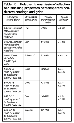
To meet the EMC requirements of BSEN-55011 and CISPR 11, it is often necessary to shield the display system. Because the medical display must be viewable, a conductive ground plane with satisfactory photopic properties must be used. Common RF shielding techniques include integration of transparent conductive coatings or a fine conductive grid over the front of the display. See Table 3 for common properties of different optical ground planes.
Conductive coatings
Transparent thin-film conductive coatings are typically transparent conductive oxides (TCOs), such as indium tin oxide (ITO). Increasing the conductivity of the coating will increase the average RF attenuation levels. Typical conductivities for transparent thin-film conductive coatings for this purpose range from 1 Ω/sq to 100 Ω/sq.
There is an inverse relationship between light transmittance and conductivity. To offset most of the transmission losses and to minimize reflections, a conductive coating can be fully integrated into a multi-layer dielectric stack as part of a broadband antireflection (AR) coating. This is commonly referred to as “index matching.” A fully enhanced TCO can have a total luminous reflection of L ) of >95% to be realized (see Table 3 ).
Table 3. Relative transmission/reflection and shielding properties of transparent conductive coatings and grids

While fine conductive grids (FCGs) offer excellent EMI shielding and good optical properties, it is most common to use them in medical equipment and enclosures associated with MRI rooms where very high levels of RF shielding are required. A FCG pattern is typically made of plated woven stainless steel, or with a patterned/etched metal coating. Both technologies have high open areas and excellent conductivities (from 100 mΩ/sq to
Advertisement
Learn more about Dontech


