Circuit protection of IP-networked security camera systems
To ensure that the security system components and network function reliably over the lifetime of the installation, transient protection (ESD and surge) should be considered
BY JIM COLBY, CHAD MARAK, and PHILLIP HAVENS
Littelfuse
www.littelfuse.com
Security cameras and surveillance systems are everywhere today, and their use continues to increase. This expansion is being driven by a number of factors including public and private institutional security and risk mitigation demands, new insurance industry requirements, and ever-increasing system capabilities along with decreasing costs.
In the past, surveillance systems often required professional installation, and involved special cabling and separate power supplies. Today’s IP-enabled surveillance systems are designed to be installed with far greater ease and flexibility, and to connect into existing Ethernet infrastructure using common CAT5 cabling or WiFi. Today, a complete system can be put together using off-the-shelf IP cameras networked into a DVR (digital video recorder) or cloud storage service, and include live remote monitoring capabilities from any web-enabled smart phone or other portable device.
Power over Ethernet (PoE) has also experienced increased growth in usage and power delivery capabilities, making it possible to power and connect cameras through a single cable thereby lowering installation costs.
Cameras are installed both indoors and outdoors to protect facilities such as apartment and office buildings, factories, school campuses, and individual residences as well as to monitor traffic conditions. In all instances, there will be a threat from electrostatic discharge (ESD) and CDEs (cable discharge events) during the cabling and uncabling activities. Vulnerable circuits include buttons and switches, memory slots, and the video output ports. For those installations that are outdoors, there will also be exposure to severe and repeated lightning transients found on the video (CVBS or SDI) and data (Ethernet, USB) ports.
Likewise, the video recording hardware (DVR/PVR unit) will be exposed to both ESD and lightning surges. When the unit is being connected to the video and data ports, ESD can be introduced by the installer. During lightning storms, transients can be introduced into the power (ac/dc) circuit and Ethernet/video ports (if connected to cameras installed outdoors).
All this presents an increasing challenge to hardware designers and manufacturers. As equipment of all types has increased in capabilities, so too has the complexity of the chipsets and their sensitivities. At the same time, there are pressures to keep unit costs low.
In many cases, the inclusion of transient protection is not considered in the early design stage, leaving the manufacturer vulnerable to failed equipment and associated warranty return costs, disposal concerns and damaged brand reputation. The intent of the protection components are to dissipate the transient energy to safe levels and ensure reliable performance of the application, while not interfering with the normal operation of the circuits. For example, they must not degrade the high-speed signals by adding excess capacitance or other nonlinear effects.
This article will discuss the threats facing each element of a security surveillance system (A through D in Fig. 1 below) and the best ways to protect against them. To view an interactive version of Fig. 1 that includes links to detailed circuits diagrams as described in this article, visit:
www.littelfuse.com/application/IP_Camera_DVR/application-diagram.html
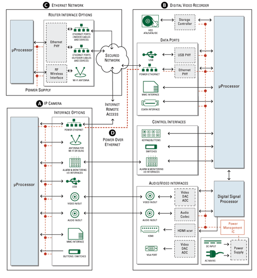
Fig. 1: Elements of a security surveillance system.
A. Protecting the camera
Electrostatic discharges (ESD) and other transients and surges can enter the camera’s DC input (if a separate power supply is used). The solution is a general-purpose transient voltage suppression (TVS) diode connected as close to the camera’s dc-input port as possible. A typical choice would be a 30-pF 30-kV unidirectional or bidirectional device rated for a standoff voltage of 5 to 6 V. The diode should be selected by choosing a voltage rating at least 15% above that of the dc circuit, considering applicable local standards, and anticipated temperature ranges.
The multimedia card (MMC) or smartcard port interface is a gateway for ESD to enter the system. The user or installer can accumulate a static charge that can transfer when the MMC or SD memory card is plugged in. Here the recommended protection is by a 8 to 30-pF 15-kV unidirectional TVS array with a standoff voltage of 5 to 5.5 V. Since this is a relatively slow speed port, the protection can be selected with a capacitance value of up to 30 pF. Selections include discrete diodes, as well as arrays that can be used to reduce parts count or save board space.
ESD can also enter through the camera’s keypads and control buttons. These can be protected by an 8 to 30-pF 15 to 30-kV bidirectional or unidirectional TVS array with a standoff voltage of 5 to 6 V. Since these are simple dc circuits, the capacitance of the protection does not matter, and the selection is based more on form factor (discrete vs array, or package outline).
In the event that a USB port is included in the camera, the data lines should be protected with a low-capacitance solution as the data rates may be as high as 480 Mbits/s for a USB2.0 and as high as 5 Gbits/s for USB 3.0. In this case, a number of array options are available with capacitance ratings well below 1 pF (see Figs. 6 and 7).
B. Protecting the recorder
Cameras that use analog video protocols like CVBS (composite video baseband signal also known as color, video, blanking, and sync) or SDI (serial digital interface), and especially those that are installed outdoors will need the protection to be robust enough to survive lightning transients. As shown in Fig. 2 , SIDACtor devices can be used for standard-definition implementations, and as shown in Fig. 3 , GDTs can be used for high-definition circuits
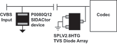
Fig. 2: Circuit protection of CVBS interface.
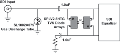
Fig. 3: Circuit protection of SDI interface.
For the ports that interface the recorder to external storage, remote access, or displays, the data rates will be very high. In these cases, the protection device must have a capacitance value low enough that it does not interfere with the signal integrity of the respective port.
Examples of these ports include HDMI (Fig. 4 ), eSATA (Fig. 5 ), USB (Figs. 6 to 7) and Ethernet (Fig. 8 ).
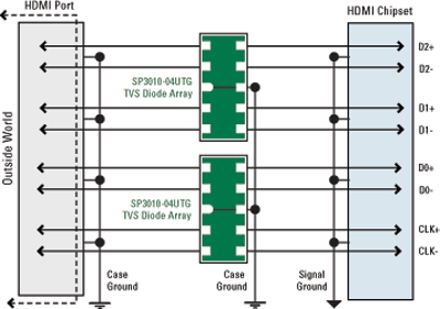
Fig. 4: Circuit protection of HDMI interface.
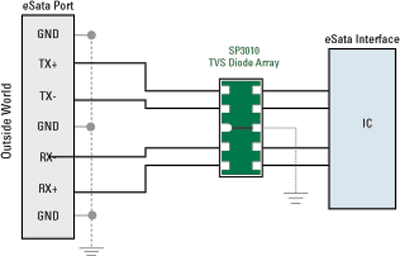
Fig. 5: Circuit protection of eSATA interface.
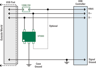
Fig. 6: Circuit protection of USB 2.0 interface.
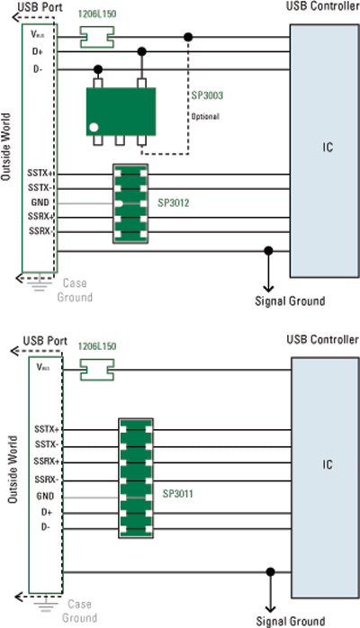
Fig. 7: Two alternative circuit protection solutions for an USB 3.0 interface.
Ethernet applications, including Power over Ethernet (PoE), is covered in more depth in the following sections.
C. Ethernet protection
The protection of Ethernet circuits will be handled in greater detail as its implementation (indoor vs outdoor) will determine the level of robustness that is required by the protection element. The basic question to be answered is whether the user is the only threat (ESD consideration), or whether the port will be exposed to lightning transients. For installations in which the Ethernet port will be connected to a local router or to a camera that is located within a facility, there is little likelihood of lightning coupling into the circuit so ESD is the only threat. In this case, the protection should be a device with capacitance of about 4 pF or less since the data rate is greater than 100 Mbits/s. An example is shown in Fig. 8.
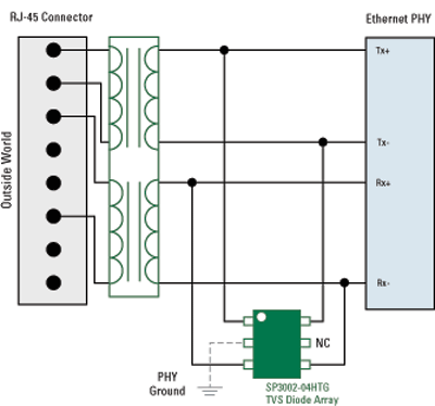
Fig. 8: Circuit protection of Ethernet interface: Indoor connection between networked device and nearby router.
For installations in which there will be long cable runs (100 m), and where Ethernet hardware will be mixed with electrical hardware and circuits (utility cabinet), standards like GR-1089 will apply. In those cases, the intrabuilding specification is the most relevant and it includes provisions to use surges up to 100 A of peak pulse current (for a 2/10-µs waveshape) for a two-pair interface such as 100Base-T, but a peak pulse current of 36.4A per wire (1.2/50-8/20-µs waveshape) for a four pair system such as 1000Base-T. For this case, the protection must be substantially more robust, and may require a cascaded approach as shown in Fig. 9 .
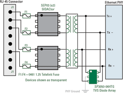
Fig. 9: Circuit protection of Ethernet interface: Intrabuilding lightning immunity through TVS diode array.
If the circuit includes a transformer capable of withstanding and limiting the lightning transient, it may be possible to only use PHY-side protection as shown in Fig. 10 .
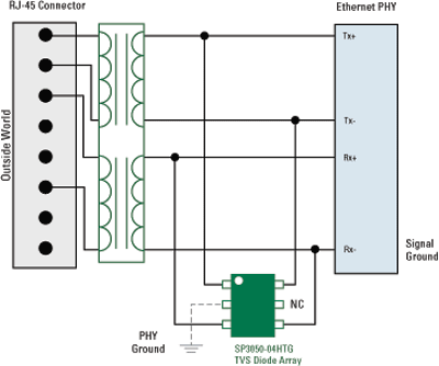
Fig. 10: Circuit protection of Ethernet interface: Ethernet interface PHY-side transient protection with lightning suppression-capable transformer.
For Ethernet installations in which the cameras will be installed outdoors, the likelihood of directly coupled lightning transients is very high. An example of a standard that covers this case is GR1089 interbuilding specification. In this case, the lightning surge is defined as having a 500-A peak pulse current (for a 2 x 10-µs waveform). Due to the extremely high levels of energy, a SIDACtor-based solution will be required for the line-side protection. For the PHY-side of the transformer, a diode array is installed to “mop up” any energy that is let through by the line-side protection. An example of this cascaded protection scheme is shown in Fig. 11 .
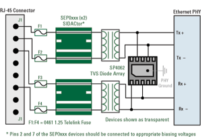
Fig. 11: Circuit protection of Ethernet interface – Inter-building lightning transient suppression.
D. Power over Ethernet
As mentioned earlier, the key aspect with respect to ease-of-installation for many of today’s surveillance camera systems is Power over Ethernet (PoE). As should be expected, this will add another facet to the protection scheme, which is not found in standard data-only Ethernet circuits. Namely, a power supply will be connected to the Ethernet lines on each end of the installation. One side is the power-sourcing equipment (PSE) that provides the power. The other side is the powered device (PD) that uses the power (e.g., IP camera).
Protection of the power supply (PSE or PD) is in addition to the protection of the data lines. In other words, protect the data lines according to the type of installation (ESD-only or surge+ESD), and add power supply protection according to their own needs. Also, take into account how the power will be implemented (Mode A or Mode B).
Mode A and Mode B implementations refer to the how the power will be place onto, and taken off of, the Ethernet circuit. For 100Base-T Ethernet, only two of the available pairs are used. The other two pairs are spare, and unused. For Mode A PoE, the power will be implemented on the spare pair. In Mode B installations, the power will be implemented on the data pairs. Lastly, it should be noted that the orientation of the dc-power signal (up to 57 Vdc) is not specified. It can be inserted in either polarity.
The most common solution for power supply protection is to use a bidirectional TVS Diode across the input to the power supply. A bidirectional diode is chosen so that it will stand off the line voltage, regardless of the polarity. Figure 12 illustrates how the TVS diode is placed in the circuit for a powered device, that must be compatible with both power mode A and power mode B, since the PSE controls the specific implementation. The PD is required to be compatible with both modes. This solution also implements an overcurrent protection device for those applications that must comply with safety standards such as UL 60950-1. For a more robust protection solution, the SMB, SMC, or SMD version can be used in place of the SMAJ58CA.
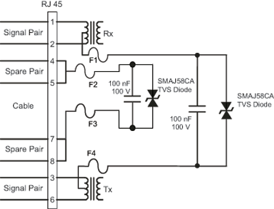
Fig. 12: Power over Ethernet power supply protection with TeleLink fuses.
In installations where inter building surges are expected, it is likely that a more robust solution is required. Since the energy in these surges will exceed the capability of most standard single TVS diodes, a high-speed thyristor device such as the Littelfuse SIDACtor family should be considered. The SIDACtor thyristor device shown in Fig. 13 offers bi-directional protection and will provide protection for both mode A and mode B. This solution is also applicable for PoE+ (IEEE 802.3at)
The PoE PD or PSE can be protected against lightning surges with a bidirectional thyristor surge protection device. In this case, pins 2 and 7 of the SEP device must be connected together on the PCB,
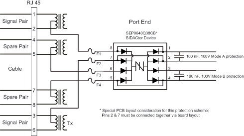
Fig. 13: Interbuilding PoE power supply protection with TeleLink fuses.
Faster computing, Power over Ethernet, and lowering equipment and installed costs, have made it possible to install sophisticated surveillance systems virtually anywhere.
In order to ensure that the security system components and network function reliably over the lifetime of the installation, transient protection (ESD and surge) should be considered. In most instances only basic ESD protection is needed, whereas equipment or cabling exposed to open outdoor environments should include addition protection against lightning surge threats. Power supply circuits will also be exposed to transient voltage events and need to be factored for protection. For all of these cases, a number of solutions exist that allow board designers to have flexibility in the design process. ■
Advertisement
Learn more about Littelfuse


