CIRCUIT FUNCTION AND BENEFITS
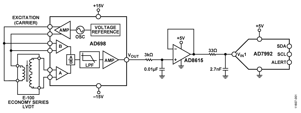
The circuit shown in Figure 1 is a complete adjustment-free linear variable differential transformer (LVDT) signal conditioning circuit. This circuit can accurately measure linear displacement (position).
The LVDT is a highly reliable sensor because the magnetic core can move without friction and does not touch the inside of the tube. Therefore, LVDTs are suitable for flight control feedback systems, position feedback in servomechanisms, automated measurement in machine tools, and many other industrial and scientific electromechanical applications where long term reliability is important.
This circuit uses the AD698 LVDT signal conditioner that contains a sine wave oscillator and a power amplifier to generate the excitation signals that drive the primary side of the LVDT. The AD698 also converts the secondary output into a dc voltage. The AD8615 rail-to-rail amplifier buffers the output of the AD698 and drives a low power 12-bit successive approximation analog-to-digital converter (ADC). The system has a dynamic range of 82 dB and a system bandwidth of 250 Hz, making it ideal for precision industrial position and gauging applications.
The signal conditioning circuitry of the system consumes only 15 mA of current from the ±15 V supply and 3 mA from the +5 V supply.
This circuit note discusses basic LVDT theory of operation and the design steps used to optimize the circuit shown in Figure 1 for a chosen bandwidth, including noise analysis and component selection considerations.
Download Full Block Diagram Below
Advertisement

Learn more about Analog Devices


