Comparing active PFC and passive attenuation
Two methods help comply with EN61000-3-2 but each has advantages and disadvantages
BY JOHN KOVACS
Vicor, Andover, MA
http://www.vicorpower.com
Poor power factor associated with electronic power conversion equipment is caused by nonlinear circuit elements. In most off-line power supplies, the ac/dc front end consists of a bridge rectifier followed by a large filter capacitor.
With this circuit, current is drawn from the line only when the peak voltage on the line exceeds the voltage on the filter capacitor. Since the rate of rise and fall of the current is greater than that of the line voltage, and the current flows discontinuously, a series of predominantly odd harmonics is generated third, fifth, seventh, etc.
It is these harmonics that cause the problems with the ac power distribution system (overheating the transformers, wires, etc). The European Union has implemented the EN61000-3-2 standard to protect its ac power distribution grid.
For the last few years, compliance to EN61000-3-2 has been required to do business within the EU. This standard places upper limits on the amount of harmonic currents certain products may generate. The purpose of this limitation is to minimize degradation of the ac mains caused by excessive harmonic currents.
These harmonic currents are metered by the utility company and included in the electric bill you pay, even though they are not doing any useful work.
Historically, ac/dc power supplies were classified as Class D products under this standard. This class of products has harmonic current limits that vary in direct proportion to the amount of power drawn from the ac line. In order to attenuate the harmonic currents sufficiently to meet the varying limits of this standard, a technique called power factor correction (PFC) has been universally used. This technique results in an offline switch-mode power supply with a near-unity power factor and with very low harmonic currents. Active PFC circuits can be complex and, because they are active, they can generate considerable EMI and require extensive filtering.
It is important to note that the EN specification does not refer to power factor nor does it require power factor correction or set any power factor limits: it only sets limits on harmonic currents. However, since active power factor correction has been the de facto method for complying with the harmonic current limits, the term PFC has been generally accepted to not only mean power factor corrected but also to mean EN compliant.
Amendment 14 to EN61000-3-2 reclassified ac/dc power supplies from Class D to Class A, eliminating the variable limit placed on harmonic currents. That limit is replaced with a fixed limit based only on the maximum input power of the class, which is 1,000 W. Since, in effect, ac/dc power supplies drawing less than 1,000 W have had their harmonic current limit increased, passive alternatives are now available to compete with active PFC for achieving EN61000-3-2 compliance.
It is useful to compare the active power factor correction method with the passive harmonic currents attenuation method.
Active PFC
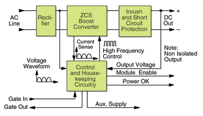
An active harmonic attenuator module (see Fig. 1) consists of a full-wave rectifier, a high-frequency zero-current switching (ZCS) boost converter, active inrush current limiting, short-circuit protection, control, and housekeeping circuitry.
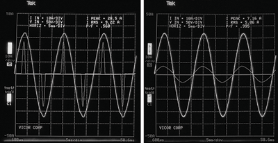
The incoming ac line is rectified and fed to the boost converter. The control circuitry varies the operating frequency of the boost converter to maintain the output voltage of the harmonic attenuator above the peak of the incoming line, while forcing the input current to follow the wave shape and phase of the line voltage. The ac input current follows the voltage waveform and a power factor better than 0.99 is achieved (see Fig. 2 ).

Fig. 1. An active harmonic attenuator module consists of a full-wave rectifier, high-frequency zero-current switching boost converter, active inrush current limiting, short-circuit protection, control, and housekeeping circuitry.

Fig. 2. Input voltage and current waveforms without (left) and with (right) power factor correction.
Passive harmonic attenuation
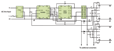
A passive harmonic attenuation method for compliance to EN61000-3-2 standards consists of an autoranging ac/dc front-end module and a passive harmonic attenuation module (see Fig. 3 ). This solution provides transient/surge immunity, harmonic current attenuation, and EMI filtering, in addition to the power switching and control circuitry necessary for autoranging rectification, inrush current limiting, and overvoltage protection.
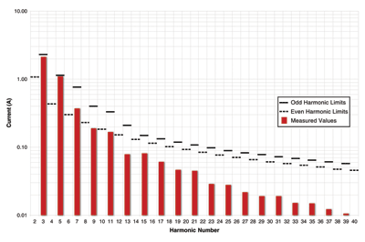
Adding a series inductor upstream from the hold-up capacitor will lengthen the conduction angle of the capacitor during the charging cycle. This reshaping of the ac current waveform minimizes the generation of ac harmonics (see Fig. 4 ), improves the power factor to the 0.7 to 0.8 range, and provides compliance to:
• EN61000-3-2 Harmonic current.
• EN55022, Level B conducted emissions.
• EN61000-4-5 Surge immunity.
• EN61000-4-11 Line disturbances.
• EN6100-3-3 Inrush current.

Fig. 3. Offline power supply configuration using passive harmonic attenuation.

Fig. 4. Harmonic currents vs. EN61000-3-2 limits.
A comparison of passive vs. active
Both methods offer compliance to the EN standard, but both methods have advantages and disadvantages.
Essentially, the passive approach using a high-inductance low-Q choke for passive harmonic current attenuation enables EN compliance for power solutions needing up to roughly 700-W input power. It’s a simple, robust, reliable, and inexpensive method of harmonic current reduction that can be employed in many lower-power systems. It requires, however, bulky low-frequency magnetics, and it can’t accommodate the universal input voltage range although autoranging is applicable for the majority of applications today.
Active power factor correction practically eliminates the ac line current harmonics, achieving near-unity power factor, and it can accommodate a universal input voltage range. It is often more costly with more complexity in the design, however, and has lower efficiency. ■
Advertisement
Learn more about Vicor


