By JIT LIM, Product Manager
Keysight Technologies
The basis for most wired, inter-device communication in consumer electronics today is the Universal Serial Bus, or USB. But major changes are afoot: Enhanced SuperSpeed-Plus USB3.1 Gen 2 doubles the SuperSpeed Gen 1 bit rate from 5 to 10 Gb/s. With Gen 2’s 128/132-bit encoding, versus the 8/10-bit coding of Gen 1, the effective throughput for Gen 2 is 2.5 times that of Gen 1.
In conjunction with USB 3.1’s promulgation, a new connector — USB Type-C — has been introduced. Its ALT mode capability enables it to transmit not only USB signals, but also Thunderbolt, DP, and MHL signals over the same connector.
This article, which focuses on how to perform transmitter characterization for next-generation USB, exemplifies the type of careful testing that Gen 2 needs. But bear in mind that any complete characterization of a USB 3.1 link requires other test systems, including EDA design simulation tools, BERT custom-link training and receiver test solutions, and network analyzers for characterizing the cables and connectors.
A full-link-testing perspective
The first step in comprehensive transmitter characterization is not to simply look at the output of the transmitter, but also to understand how the signal would be seen at the end of the link, inside the receiver. This requires understanding and incorporating all the components that the signal traverses within the link:
• the link protocol
• transmitter equalization
• spread-spectrum clocking
• compliant channel
• the reference receiver
Understanding and testing to the specs of these individual link components provide insight to comprehensive transmitter characterization.
Link protocol
In addition to supporting USB 3.1 Gen 2 speeds, the Type-C connector must support USB 2.0, 3.0, and USB 3.1 Gen 1 speeds. USB 2.0 signals are transmitted over the D+/D- lines and the USB 3.0 and 3.1 signals over the TX differential pairs (Fig. 1 ).
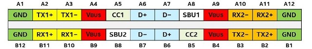
Fig. 1: In USB 3.1, the pins of Type-C connectors are assigned the signals shown above.
This requires the link partners to declare and negotiate their appropriate capabilities. To achieve 10-Gb/s signaling, the LTSSM (Link-Training-Status State Machine) must correctly transmit and identify LFPS (Low-Frequency Periodic Signaling), SCD1/SCD2 (SuperSpeed Capability Declaration), and LBPM (LFPS-Based PWM Message).
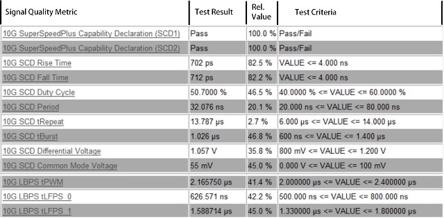
During the test, a BERT is used as a link partner, and it sends the LTSSM signals to the receiver inputs of the device under test (DUT). The response from the DUT TX is then analyzed by the transmitter-compliance analysis software. The precise burst timing, interval, and signal quality metrics (like rise/fall time) are tested to ensure adherence to specification requirements (Table 1 ).
Table 1: Typical test results from LTSSM compliance analysis software.
Transmitter equalization
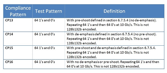
With the increased bit-rate, additional transmitter equalization is required to negate loss in the channel. USB 3.1 Gen 2 specifies a 3-tap FIR Equalizer with normative (required) 2.2 ± 1.0 of Preshoot and -3.1 ± 1.0 De-emphasis. To characterize the transmitter equalization, compliance patterns CP13 through CP16 are used (Table 2 ). A BERT or Pattern Generator is used to generate the ping.LFPS signal required to toggle the DUT to output the various compliance patterns.
Table 2: Compliance patterns for transmitter equalization (From USB-IF).
Precise implementation and characterization of the transmitter preshoot and de-emphasis are required to properly compensate for the losses in a USB cable or connector, such as that shown in Table 3 .
Table 3: Proper pre-shoot and de-emphasis for transmitter characterization from a compliant DUT.

Spread-spectrum clocking
To reduce EMI, USB 3.1 DUTs always operate with spread-spectrum clocking (SSC) enabled. Combined with separate clock architecture between the link partners, the asynchronous clock domains significantly reduce margin in the receivers. The CDR in the receiver is slew-rate limited in tracking and rejecting low-frequency jitter. Therefore, the TX SSC df/dt, modulation frequency and modulation rate have to be carefully characterized, as in Fig. 2 .
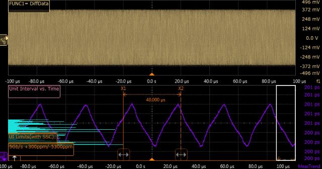
Fig. 2: Plot of SSC modulation profile.
Compliant channel
To test a 10 G Host with a USB Type-C to Type-C connector, channel compliance must equal 14.5 dB of loss. This loss would be from the output of the Host/Tx Type-C connector (8.5 dB) and include any cables, connectors, adapters, and test fixtures (6 dB).
The traditional approach is to build a complete hardware-compliant channel using a combination of test fixtures, cables, connectors, and variable ISI channels to achieve the required loss. Another approach would be to use a test fixture with the highest signal integrity and software-embed the compliant channel. The same requirements apply even if USB Std A-type connectors are used for the Host, and the Host communicates to Std B or Micro B connectors on the device side.
Signal quality tests
Some of the TX tests are performed at the output of the transmitter. However, many of the TX tests are performed at the end of the link and also incorporate receiver characteristics, such as receiver equalization and receiver clock recovery.
Signal quality measurements like random jitter (RJ), total jitter (TJ, random plus deterministic jitter), eye width, and eye height provide quantitative data about the physical layer performance of the link. In addition, they provide insight into the root cause of the eye closure by isolating and decomposing the various jitter components.
Similar to the transmitter equalization measurements mentioned above, the signal quality tests require specific compliance patterns. Generally, a clock pattern is required for performing RJ analysis, and a PRBS pattern is required for TJ, eye width, and eye height.
To add a compliant receiver to the link, the reference CTLE and DFE are applied to the waveform before analysis. Similarly, a reference-clock recovery is also applied to the waveform before analysis to remove SSC and other low-frequency jitter components. In contrast, in the SSC analysis discussed previously, no clock recovery is performed, and we are focused on characterizing the full jitter spectrum of the transmitter. In signal quality tests, we test the ability of a reference receiver to recover the clock, remove the low-frequency jitter, equalize, and recover a worse-case compliant signal. The desired result would resemble those in Table 4 , with an eye diagram like that in Fig. 3 .
Table 4: Signal quality results from a compliant DUT.
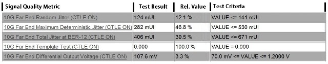
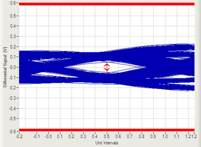
Fig. 3: Eye diagram for a worst-case compliant signal.
Advertisement
Learn more about Keysight Technologies, Inc.


