BY BRUCE ROSE, Applications Engineer
CUI
www.cui.com
One of the design activities often left to the end of a project is verifying that the product meets electromagnetic compatibility (EMC) emissions requirements. But while delaying EMC compliance testing until the end of the project is a common practice, it can lead to significant unexpected costs and project delays. These can be avoided by considering EMC compliance earlier in the design process.
Often, the reason EMC testing is put off until the end of a project is due to time, cost, and workload constraints. Unfamiliarity with compliance testing also contributes to the perception of the difficulty of such testing. (See “A brief introduction to electromagnetic compatibility in product design ” for a quick overview.) Fortunately, while the required equipment and facilities for EMC compliance testing can be unique, many testing labs are available with experienced staff to assist in the testing.
The costs associated with compliance testing often become a “pay-me-now-or-pay-me-more-later” event. As testing is usually done at the end of development in order to obtain full certification of the final design, this cost can be high. Final testing of conducted and radiated emissions needs to be performed in a certified laboratory using calibrated test equipment and a controlled electrical environment. Availability of lab time for full certification testing can also be an issue as many labs are booked up several weeks out.
But delaying the discovery of system-conducted and -radiated EMC issues until the end of a project puts their correction into a phase in the schedule that is perhaps the worst time to introduce unexpected tasks and delays. A more reasonable and often lower-cost strategy is to perform preliminary EMC compliance testing as soon as the system assembly has begun. Earlier in a project, schedules are more flexible and design teams are more receptive to modifications in the design. Similarly, availability of small blocks of time for preliminary testing typically can be found at otherwise booked certification labs outside of their peak hours.
For preliminary screening, the cost is minimal and testing labs will cooperate to perform pre-compliance testing early in the design phase. The small amount of resources spent performing preliminary EMC testing early in the design cycle can thus prevent considerable and expensive redesign efforts that would occur if EMC issues are only caught late in the product schedule.
Pre-compliance testing
While full-compliance testing requires a certified laboratory, if a design team desires to conduct the pre-compliance testing themselves, the tests can be performed in a room with a minimal amount of test equipment. The equipment required for conducted emissions testing is a line impedance stabilization network (LISN) and a spectrum analyzer. The LISN is a passive network used to minimize the noise conducted from commercial power lines. It also provides a controlled impedance test port to monitor the conducted emissions from the equipment under test (EUT). The spectrum analyzer used for conducted emissions testing can be a basic model with the ability to perform measurements from 150 kHz through 30 MHz. Many vendors of spectrum analyzers include the ability to perform quasi-peak measurements and incorporate conformance parameter limits in the display to simplify EMC compliance testing.
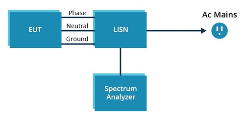
Fig. 1: Conducted emissions test setup.
Preliminary testing for radiated emissions can be accomplished with a spectrum analyzer and an appropriate antenna. The spectrum analyzer should have the capability to make measurements from 30 MHz through at least 900 MHz. The ability of the spectrum analyzer to perform quasi-peak measurements and display conformance parameter limits in the display will make the preliminary testing tasks easier to perform. The antenna used for preliminary radiated emissions testing should have a bandwidth similar to that of the spectrum analyzer, and the antenna’s gain-versus-frequency characteristics need to be known. It is preferable to be able to perform the radiated emissions testing in an electrically quiet room with at least three meters (10 feet) between the radiated emissions EMC antenna and the EUT. An initial measurement in the room with the EUT powered off will provide information regarding the ambient RF noise present during the testing.
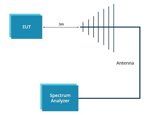
Fig. 2: Radiated emissions test setup.
An example will help illustrate the benefits of early testing. One common reason for delaying the EMC testing of a system is the misconception that the power supply is the cause of most EMC issues. Thus, the thinking goes, a system will pass testing if the supply has already passed standalone regulatory testing. This misconception arises in part from the fact that almost all power supplies are based on switching regulator topologies, and a switching regulator inherently produces conducted and radiated emissions that need to be mitigated in the design of the supply. In many instances, however, the power supply receives the blame for EMC issues within the system when, in reality, it is “only the messenger.”
Even so, by the end of a project, much effort has been applied to designing the system to meet performance criteria, and if an EMC compliance issue arises, the power supply is perceived as the easiest target for compliance correction efforts without affecting other system performance parameters. This perception arises even though the system is often the source of RF emissions because the cabling on the input and the output of the power supply may be serving as antennas for radiated emissions and conductors for conducted emissions.
It is often possible to add noise-suppression components to the power supply to address such EMC issues, which is the path that many design teams end up taking. For products that use internal power supplies, EMC noise-suppression components can be added either on the conductors feeding into the power supply or on the cabling between the output of the power supply and the power input to the system. Bypass capacitors and ferrite cores are suppression components used to create filters to address EMC issues. Ferrite cores introduce additional inductive impedance in series with the path of the unintended noise, and bypass capacitors provide a low-impedance path to shunt noise signals to minimize signal propagation.
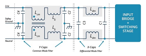
Fig. 3: Conducted emissions filter components.
Systems employing external power supplies may be more limited in their ability to add EMC suppression components on the input or output paths of the power supply. Radiated emissions issues are typically addressed with a ferrite core placed on the cable between the power supply and the system. But the frequencies of concern associated with conducted emissions are low enough such that the size of a ferrite core required to fit around a power cord and mitigate EMC issues will be unacceptable for many applications. Conducted emissions issues observed in systems with external power supplies are often most easily addressed by working with the power supply vendor to modify the design of the existing supply or selecting a different external power supply incorporating enhanced conducted emissions suppression components. Full-service power supply vendors, such as CUI , have the equipment and experience to assist in power supply design and selection, including pre-compliance and final EMC testing.
But all this end-of-project activity should be recognized as mitigating the effects of the problem and not addressing the source of the problem. Furthermore, the EMC suppression activities associated with the power supply will still require time from the design team and may also affect the safety certificates associated with the power supply. Any changes to the safety certificates will then require time and resources from the power supply vendor, adding yet more to the project cost. And after all of that, the system circuitry may still need to be modified to minimize the generation of RF signals if adding conducted and radiated emissions suppression components is insufficient to adequately reduce the EMC problems.
Most management teams appreciate projects completed under budget and ahead of schedule. Unfortunately, EMC compliance issues can be a common source of last-minute budget and schedule increases for projects when testing is delayed until the end. Performing pre-compliance EMC testing during the system assembly phases of a project can help to eliminate those last-minute changes to a design that impact budgets and schedules. Pre-compliance EMC testing also helps to ensure that no issues arise during final compliance testing, helping to keep this project phase on time and in budget.
Advertisement
Learn more about CUI Inc


