Implementing the required power infrastructure for an ATCA board can be a daunting task
BY BRAD SUPPANZ
Power-One, Camarillo, CA
http://www.power-one.com
The AdvancedTCA specification calls out a well-defined set of power management requirements to provide specific interfaces to the shelf manager, which controls the on/off status and monitors each ATCA board’s power subsystem. Each board requires a redundant –48-V feed with EMI filtering, safety isolation, inrush limiting, and enough holdup to ride through a 5-ms short on both inputs.
The solution must also be hot swappable and negotiate power consumption with the shelf manager while consuming less than 10 W from a 3.3-V typ power supply with management, control, and monitoring interfaces provided via a redundant IPMB-0 bus. Monitoring includes voltage, current, temperature, and threshold events that occur when an analog sensor reads outside of a pre-defined window.

Engineers increasingly turn to programmable building-block approaches using POL converters and digital management.
In addition, the board’s payload circuitry typically involves several low-voltage/high-current supplies that need sophisticated features such as sequencing/tracking, fault management, and margining. To avoid designing an ATCA board’s power subsystem completely from scratch, engineers are increasingly turning to highly integrated programmable building-block approaches using POL converters and digital power management.
Digital power management
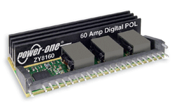
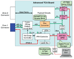
ATCA power systems require complex control and monitoring capabilities and must support the sequencing/tracking and fault protection requirements of the payload circuits. One solution is to use a digital ATCA power subsystem such as the Z-One solution, in which digitally controlled POLs receive a 12-V intermediate-bus voltage from a bus converter.
In such a system, an LDO steps the 12 V down to 3.3 V to be used for the controller ICs. Voltage, current, and temperature monitoring are performed in each POL, and the measurements and fault status are transmitted to the digital power manager (DPM) via a one-wire sync/data (SD) line. This approach helps to minimize the parts count, and since it does not require any discrete sequencing FETs, A/D or D/A converters, or current and temperature sensor circuits, this solution is also very compact.
Development, verification, and testing are supported by a GUI that includes simulation features that reduce the time needed in front of an oscilloscope. Most digital power management systems have a design wizard to allow the POLs to be easily configured with the desired output voltages, margining, sequencing/tracking, and fault protection.
In the case of the Z-One system, all of the configuration data are stored in flash memory in the DPM and transferred to the POLs at power-up over the SD line, which also synchronizes all of the POLs so they can run at the same frequency or a multiple thereof. Phase lag may also be applied to allow interleaving of the POLs’ switching. This control over the switching/phasing of the POLs minimizes the system-level switching noise and eliminates beat frequencies that can wreck havoc in a system using unsynchronized POLs.
All ATCA boards require an “intelligent” hardware management system based on the Intelligent Platform Management Interface (IPMI) specification. The IPM controller (IPMC) implements these IPMI features to manage the power and interconnect needs of the ATCA board as well as to monitor and log events to a central repository.
The IPMC is typically a microcontroller and may be a drop-in reference design that includes firmware that implements the basic IPMI stack with some customized firmware being required to handle the specifics of the board. The DPM greatly simplifies the custom firmware in the IPMC by taking on all power subsystem tasks and providing a simple monitoring and control interface.
Communication
In a digital power management system such as the Z-One, the DPM and the IPMC communicate over a standard I2 C bus. This same bus provides the interface to the GUI during development. It is worth noting that the DPM takes care of all POL sequencing, data gathering, and so forth, and provides a very simple I2 C interface to the IPMC.
Programmed via the GUI software, the DPM requires no firmware to be written for it, which also greatly reduces the amount of application-specific firmware that needs to be developed for the IPMC. The IPMC can be configured to pass configuration settings to the DPM to allow field updates.
The IPMC talks to the off-board shelf manager using a bus called IPMB-0, which is essentially a dual-redundant I2 C bus with special message protocols. The IPMB-0 bus passes through the Zone 1 connector of the ATCA board. The Zone 1 connector also brings in the –48-V supply, which may be redundant.

Engineers increasingly turn to programmable building-block approaches using POL converters and digital management.
The two –48-V inputs are fused, diode OR’ed, and passed through an inrush limiter to a holdup capacitor bank and EMI filter. Control and monitoring of all the circuitry upstream of the bus converter are done by the hot-swap controller, and status information can be passed to the IPMC. These functions are sometimes lumped together as a power input module (PIM).
Advanced Mezzanine Cards
Advanced Mezzanine Cards (known as AdvancedMCs or AMCs) come in several standard widths and heights, and up to eight AMC modules can be plugged into an ATCA carrier board or 12 into a MicroTCA rack.
Each AMC module uses a very simple microcontroller called an MMC (module management controller) to communicate with the main IPMC on the carrier board via a bus called the IPMB-L (IPMB-Local) bus. This is a variation of an IPMB bus with added isolators at each plug-in location to prevent fault propagation on the bus.
Current-limiting and power-good statuses are provided for the 12- and 3.3-V terminals at each slot. Again, drop-in MMC solutions are available that require minimal firmware development to support the specifics of the AMC module. ■
For more information on power supplies, visit http://electronicproducts-com-develop.go-vip.net/power.asp.
Advertisement
Learn more about Power-One


