The FAN7529 is an active power factor correction (PFC) controller for the boost PFC application that operates in the critical conduction mode (CRM). The critical conduction mode boost power factor converter operates at the boundary of continuous conduction mode and discontinuous conduction mode. The CRM PFC controllers are of two kinds: the current-mode CRM PFC controller and the voltage-mode CRM PFC controller. For the current mode, a boost switch is turned on when the inductor current reaches zero and turned off when the inductor current meets the desired current reference.
In this case, the rectified AC line voltage should be sensed to generate the current reference, as in the FAN7527B; however, the sensing network can cause additional power loss. In the voltage mode, the switch turn-on is the same as that of the current mode, but the switch turn-off is determined by an internal ramp signal. The ramp signal is compared with an error amplifier output and the switch turn-on time is controlled to be constant, as shown in Figure 1. If the turn-on time is constant, the peak inductor current is proportional to the rectified AC line voltage, as shown in Figure 2. In this way, the input current waveform follows the waveform of the input voltage, thereby obtaining a good power factor. The FAN7529 is a voltage-mode CRM PFC controller. Because the voltage-mode CRM PFC controller does not need the rectified AC line voltage information, it can save the power loss of the sensing network.
Click here for application note
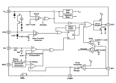
Download full block diagram below
Advertisement

Learn more about Fairchild Semiconductor


