By Will Zhou, product marketing engineer, Texas Instruments, Battery Management Systems (BMS) group, www.ti.com
The USB Type-C and USB Power Delivery (PD) specifications were first released in 2014. Since then, electronic devices equipped with USB Type-C ports supporting USB PD have become common. USB Type-C ports are engineered to support high-power capabilities with the USB PD standard, facilitating more flexible and faster charging for devices like laptops, cellphones, portable speakers, and power banks.
The USB Type-C port has flip ability and four VBUS power pins (versus one in the traditional USB Type-A and Micro-B). Compared to the previous 5-V/0.1-A to 1.5-A VBUS, USB PD offers a flexible range of power profiles from 5 V/0.1 A up to 20 V/5 A, allowing faster charging. The newest USB PD 3.0 standard added a programmable power supply (PPS) feature, with the VBUS supporting a 20-mV-or-smaller tuning step to meet the requirements of fast charging schemes like flash chargers or switched-capacitor chargers. These chargers significantly increase charging current and efficiency but also need constant VBUS adjustment to keep up with the changes in battery voltage.
With the ability to support a wide-range of power profiles and its backward-compatibility, USB Type-C/USB PD becomes a more universal charging solution, thus significantly reducing the number of different types of cables and connectors. You can use a USB Type-C/USB PD wall adapter or power bank to charge every compatible electronic device with the same cable.

Fig. 1: The pinout of the USB Type-C connector.
Buck-boost chargers for USB PD
The application’s power level will usually determine the battery-cell configuration and the USB PD power profile. Here are some typical applications across various Li-ion battery-cell configurations and power levels:
- Single-cell (1S) configuration: Mostly used in small electronics like smartphones, sports cameras, and small wireless speakers. Most of these electronics have a 5-V/3-A power profile or less; the exceptions are high-end smartphones, in which higher power and fast charging schemes are often touted as product features.
- Two-cell-in-series (2S) configuration: These applications often support higher power profiles and are usually employed by applications such as two-in-one tablets, USB PD power banks, and electronic point-of-sale devices.
- Three-cell- and four-cell-in-series (3S–4S) configurations: These batteries have higher voltages and are used in bigger devices like laptops, high-power smart speakers, and consumer drones. The common power profiles in 3S to 4S applications may get to 45 W (15 V/3 A or 20 V/2.25 A) and above.
It can be a useful feature for a multi-cell charger to support single-cell configuration as well. This flexibility allows the reuse of designs with minimal changes across products that use different battery configurations.
A buck-boost charger provides the buck, buck-boost, and boost working modes. There are two reasons why these working modes are needed in PD. The first reason has to do with the USB PD’s wide input voltage range. For example, let’s say that you want to design a battery-powered smart speaker with USB Type-C/USB PD. To make it easy to support the powerful audio amplifiers, you choose a 3S battery. You want it to be compatible with a small 5-V/2-A to 3-A travel adapter, a bigger laptop adapter with 20-V/2.25-A USB PD capability, and something in between. In the 3S configuration, the nominal battery voltage is about 11.1 V. With the 5-V travel adapter, the charger needs to boost the input voltage up to the battery; with the 20-V/2.25-A adapter, however, the charger needs to buck it down.
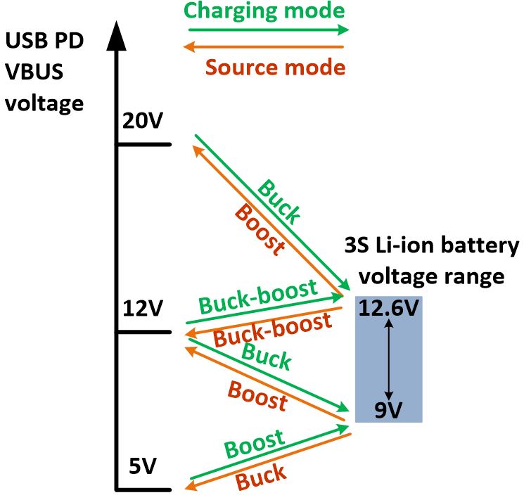
The second reason is that the battery voltage varies with different states of charge (SoC). A typical 3S battery voltage can vary from 9 mV when it is empty (0% SoC) to 12.6 V when it is full (100% SoC). If an adapter provides 12 V after power negotiation, it will be in buck mode to charge the 3S battery in a low state of charge and in buck-boost and boost mode as the battery continues to charge (the charger is in buck-boost mode when the input voltage is on a similar level to the battery voltage). Fig. 2 shows an example of the different working modes of a buck-boost charger IC with a 3S battery with different VBUS USB PD profiles and battery states of charge.

Fig. 2: Working modes of a buck-boost charger, with various input voltages and states of charge in charging and source modes.
You may sometimes need to use a USB charging port as a source device to supply power to external devices with the USB source mode (or On-The-Go mode in the past). To support USB PD as a source device, you will also need a buck-boost charger. Say that you want to add power sourcing capability to the smart speaker that you are designing. To supply 5 V as a source on VBUS, the speaker needs to step the voltage down from the 3S battery; to supply 20 V, the VBUS needs to boost up from the 3S battery. The buck-boost charger can manage both sinking and sourcing power with the same set of external field-effect transistors (FETs), making the design more feature-abundant without adding cost. To support the PPS feature in source mode in a power-bank design, for example, the VBUS needs to yield voltages in incremental steps of less than or equal to 20 mV.
How a buck-boost charger works
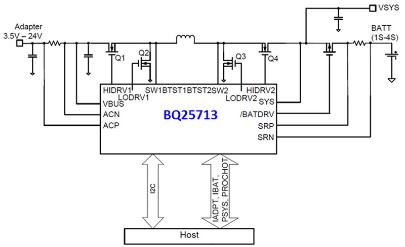
Looking at the buck-boost charger topology in Fig. 3 , there are four switching FETs that implement the buck-boost function (not to be confused with buck-boost mode, wherein the input voltage is on a level similar to the system or battery voltage). In buck mode, the Q1 and Q2 FETs keep switching to step the adapter voltage down; Q3 stays off and Q4 stays on. In boost mode, Q1 stays on, Q2 stays off, and Q3 and Q4 switch to boost up the voltage.
In buck-boost mode, when the input and output voltages are on similar levels, Q1, Q2, Q3, and Q4 will need to switch once in a cycle traditionally. The same operation principle holds true in USB PD source mode as well. Texas Instruments (TI) has an innovative technology that allows only two FETs switching once per cycle in the buck-boost mode. This technology greatly improves power efficiency and reduces heat dissipation. The pass-through mode (PTM) can further improve the efficiency by keeping Q1/Q4 always on, and Q2/Q3 always off.
In PTM, the system voltage is equal to the adapter input voltage. The input power passes through Q1, the inductor, and Q4 directly to the system with negligible switching loss and no inductor core loss. PTM can be used for high-current flash charge and for low-current light-load operations to improve efficiency.

Fig. 3: Application diagram of the TI BQ25713 buck-boost charger.
USB Type-C/USB PD charging system and design considerations
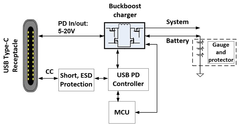
In a USB Type-C/USB PD charging system, apart from the buck-boost charger, other functional blocks may include an interface protection chip, a PD controller, a gauge and a protector for the battery, and a general controlling function for power path coordination and LED operation. The general control can be either implemented by a standalone microcontroller (MCU) or integrated into the PD controller. The USB PD controller detects plug-in events, identifies device roles, and negotiates power levels. An I2 C or SMBus interface configures the charging parameters.
The gauge and battery protector are usually inside the battery pack. The gauge measures the battery’s state of charge and can communicate with the MCU to adjust the charging parameters in real time. The battery protector implements cell balancing, voltage, current, and temperature protections and is sometimes integrated into the gauge. Fig. 4 shows the main blocks of a typical battery system.

Fig. 4: Block diagram of a battery system with a USB Type-C port.
You will need to consider charging performance and features to make your systems less heat-dissipative and more cost-effective and compatible with universal power sources. To obtain a cool charging experience, the power efficiency needs to be high in various working modes (buck, boost, and buck-boost) with different loads.
In applications in which the system needs to know parameters like input and battery currents/voltages to take action, an integrated analog-to-digital converter (ADC) makes measurements readily available. Because different USB adapters can have different power profiles and cables can have different resistances, it’s important to know the source’s maximum power capability to avoid crashing it. TI’s input current optimization (ICO) feature enables systems to capture the maximum power of a source automatically upon insertion. This feature allows the system to safely draw maximum power from various adapters, even an unknown adapter with large impedance and a long cable. The power path feature is preferred to instantly power on the system with a deeply discharged battery upon the insertion of the adapter.
Conclusion
The market demand for USB Type-C/USB PD will only continue to rise due to the technology’s ease of use and wide range of power profiles. To meet USB Type-C/USB PD charging system design needs, buck-boost chargers are needed to step up and step down the input voltages to charge the battery and supply for the system. Be sure to look for a charger that operates at high efficiency in different modes and integrates functions like ICO, ADC, and power path in your next design to achieve fast and cool charging and an optimized system solution cost.
TI’s USB Type-C/USB PD solutions include:
- BQ25713 and BQ25703A 1S–4S buck-boost chargers
- The BQ25871 battery switch charger and BQ25970 switched-capacitor battery charger for flash charging on the sink side
- The TPS65987D USB Type-C and USB PD controller
- The TPD6S300A USB Type-C short-to-VBUS protection IC
For more USB Type-C and USB PD products, check out TI’s overview page.
Will Zhou is a product marketing engineer in the Texas Instruments Battery Management Systems (BMS) group. Will has bachelor’s and master’s degrees in electrical engineering from Nankai University and the University of Florida. You can reach Will at .
Advertisement
Learn more about Texas Instruments


