Desktop Vcore inductor efficiency comparison
Efficiency comparison testing shows results of a power cube and four power beads used in desktop computer operations
BY JOHN GALLAGHER
Pulse, Power Div., San Diego, CA
http://www.pulseeng.com
Last year, the EPA introduced new Energy Star efficiency standards for desktop computing, creating a renewed interest in analyzing methods to reduce power consumption. Power supply efficiency is affected by many components, but mostly by the switching devices (FETs) and the power magnetics. The power magnetics, or inductors, are used in desktop core voltage regulators for core processor power. Historically, for desktop computing applications, low efficiency bare-coil toroid cores have been used. Recently, these have been replaced with slightly more efficient power cube inductors, and now, through-hole technology (THT) power beads have proven to be an even more energy efficient solution. This article focuses on the power inductors used in voltage regulators for core processor power and compares their efficiency.
Background
The Energy Star standard for computers revision 5.0 was finalized on November 14, 2008 and is now being implemented. In May 2009, EPA announced Energy Star requirements for computer servers that will protect the environment and result in significant energy savings. The EPA anticipates that improvements in efficiency will result in 30% reduction in energy usage. The goal of Energy Star is to reduce power consumption by setting standards for computers in idle, sleep, and standby modes. Servers and point-of-load devices, which are already geared towards performance and efficiency, have used surface mount (SMT) power beads for the last several years. Now, as a result of the new computer standard, the efficiency of the power inductors in desktop applications has been examined. As mentioned, the less efficient toroid core inductors have given way to power cubes, but due to demand for greater efficiency improvement, the power IC manufacturers have found that THT power beads can further increase efficiency.
For desktop applications there are typically two distinct power stages. The first stage, or front-end, has an isolated ac/dc power supply that converts power from the ac wall outlet to an intermediate dc voltage of 12 or 24 V or some combination of that. The second stage is a non-isolated dc/dc power supply that converts power from the intermediate rail (typically 12 V) to the 1.2, 3.3, and 5.0 V required for computer silicon. The highest power second-stage is that which powers the processor and is typically referred to as a voltage regulator (VR), or core voltage (Vcore). This power stage converts 12 V to 1.x volts with somewhere between 100- and 120-A output current with peaks up to 150 A or a total of roughly 180 W.
The ability to improve efficiency in this second stage is important because any power savings in this second stage is multiplied due to the efficiency of the front-end. So, for example, if front-end efficiency is 90%, then a 1-W savings in the dc/dc efficiency will mean a real savings of 10, 0.9 or 1.1 W.
Wound-toroid inductors (see Fig. 1a ) have been the mainstay for desktop core voltage regulators for years. Historically, the bulky size, sloppy tolerances, and high power losses of these inductors were not a concern as they had the lowest-cost, making them the solution of choice. However, as Vcore requirements evolved, three factors have highlighted the negative aspects of the wound toroid. First, the increased transient response necessitates decreasing the inductance value, which in turn drives up the inductor core losses making the toroids an even more inefficient solution. Second, placement close to the processor to minimize unwanted parasitic elements necessitates an inductor that is low enough to fit under the processor heat sink without occupying too much board space. The bulky toroid is unable to meet that requirement. Finally, the resistance of the inductors is now used as the current sense element which requires a tightly controlled resistance tolerance. Again, the hand-wound toroid with tolerances of ±10% to ±12% is unable to meet this need. Efforts to modify the toroid design to address these issues, along with broader global economic conditions, have continually increased the price of the once low-cost wound toroid. As a result, the wound toroid is now an ineffective and ultimately higher-cost choice solution for Vcore regulators.

Fig. 1a. Wound toroid inductors were mainstay of desktop voltage regulators.
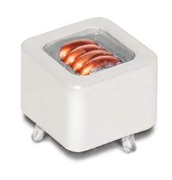
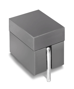
Two alternate approaches, the through-hole power cube (see Fig. 1b ) and through-hole power bead (see Fig. 1c ), have been proposed and implemented in an effort to meet the new efficiency requirements. The power cube uses the same powdered iron core material and multi-turn winding structure as the toroid, but has been re-shaped, enabling the power cube to meet the height restrictions and improve the direct current resistance (dcR) tolerance. The power bead uses a more efficient ferrite core material and has a single turn winding which allows for a smaller overall footprint and even tighter dcR tolerance.

Fig. 1b. The through-hole power cube is an alternative to the wound toroid inductor.

Fig. 1c. The power bead is another approach to the wound toroid inductor design.
Tests have been done to compare the power cube’s performance to the power bead’s.
Power cubes vs. power beads
Using power beads instead of power cubes improves overall system efficiency for several reasons. There is a significant decrease in ac and dc copper losses due to the power bead core’s single-turn structure vs. the through-hole cube inductor’s multiple turn structure. The power bead has a ferrite core, while the power cube has an iron powdered core. There is a significant decrease in ac core losses due to the low-loss ferrite core when compared with the high-loss iron powdered core. In addition, there is a tighter dcR tolerance of ±4% on the power beads compared with ±6 or ±7% for power cubes, which allows for more accurate current sensing and regulation. Due to their increased performance, through-hole power beads are used by several microprocessor and power IC manufacturers.
For the purpose of this article, direct efficiency comparison testing was performed between a power cube and four power beads commonly used in desktop computer operations. The through-hole parts used for the test were as follows:
Cube: 12.0 x 12.0 x 9.0 mm max, 300 nH, 0.8 mohms nominalBead A: 11.8 x 9.0 x 9.2 mm max, 260 nH, 0.5 mohms nominalBead B: 15.9 x 9.0 x 9.2 mm max, 280 nH, 0.62 mohms nominalBead C: 15.9 x 9.0 x 9.2 mm max, 330 nH, 0.62 mohms nominalBead D: 15.9 x 9.0 x 9.2 mm max, 360 nH, 0.62 mohms nominal
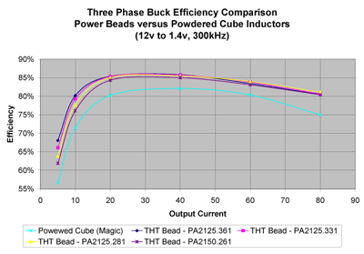
The test was conducted using a 3-phase, 12 to 1.4 V, 300 kHz demonstration board. For test purposes and to get an accurate comparison of the power cube vs. the power beads, the inductor was placed on a separate board. In actual use, the inductor is located on the same board, so the absolute efficiency will be significantly greater than that shown on the comparison curves. Comparing the efficiency to the output current, it can be seen (see Fig. 2 ) that for a light load with an output current of 10 A, the efficiency of the power cube is between 5 to 9% more efficient. For a heavy load that has an output current of 80 or 26 A per phase, the efficiency of the power cube is 75% while the efficiency of all the power beads is 80%. The beads are 5% more efficient at a heavy load.

Fig. 2. Comparison of efficiency to output current.
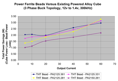
The power beads were tested for total power savings using a power cube as the basis for comparison (see Fig. 3 ). The savings were measured in watts. On average, the beads saved between 1 and 2 W of power for a light load of 10 A. The beads saved between 2 and 3 W for a full load of 80 A or 26 A per phase.

Fig. 3. Power savings of power beads.
PCB footprint size plays an increasingly important role in inductor selection as manufacturers strive to reduce board size, reduce parasitics by placing components closer to the processor, or add more components to an already crowded board. Using power bead A, board space can be reduced by 25% compared to the power cube and still enable a 2-W power savings at full load. Power beads B, C, and D use the same board space as a power cube, but enable over a 3-W power savings.
The cost of efficiency
Although the EPA encourages use of more efficient power supplies, how much extra are computer manufacturers and consumers willing to pay for this efficiency? Many green products save energy or are environmentally friendly, but there is an increased cost to the manufacturer or consumer. It can be a risk to the manufacturer to switch to a greener solution if there is a cost increase that the consumer is not willing to bear. The above data show gains of 5 to 9% efficiency when using power beads instead of power cubes. In this case, the unit price of the power beads and the power cubes is about the same. As a result, manufacturers can comply with the EPA regulations and consumers can benefit from increased computer power efficiency without incurring extra costs.
Power beads minimize inductor conduction losses because of their low dcR, while their low-loss ferrite core minimizes inductor switching losses. Their small footprint enables better board layout. Using power beads, instead of power cubes, in desktop core voltage regulators not only increases efficiency, it can save the consumer money. ■
Advertisement
Learn more about Pulse Electronics


