Detecting and managing faults in LED lighting
How to avoid system downtime when there is an open LED failure
BY GEORGE RASKO
Applications Engineer
ASIC Advantage
www.asicadvantage.com
No matter how hard engineers try to prevent it, parts fail. LEDs are no exception, and with the cost and reliability expectations of LED lighting solutions, avoiding system downtime from shorts or opens can be critical. Since LEDs are normally used in strings of multiple LEDs, an open-circuit LED causes the entire string to go dark.
Moving equipment and traffic to repair a traffic light can be a costly exercise. Lighting failures for systems dispersed in a building or over a geographical area can go unnoticed, creating hazards for security and safety. Solutions that monitor lighting systems for failures in order to increase uptime or decrease downtime are thus critical for positive customer perception and rapid adoption of LED lighting solutions.
Detection and monitoring
Managing faults first requires their detection, the most basic step for maintenance of lighting system functionality. With LEDs, voltage is the most easily measured parameter for detecting an individual LED’s status. Used for fault sensing, the on-state LED voltage serves to detect either open or shorted LEDs.
As already described, the open-circuit failure of a single LED can extend beyond the loss of lighting for a single device, extending to the loss of an entire string of LEDs based on typical configurations used for lighting. In contrast, a short can leave the other LEDs functional, reducing the likelihood of detection, though leaving the impression of an unreliable system for those viewing the failure.
Active monitoring and detection can provide system management where failures are quickly detected and repaired for minimal impact on functionality and downtime. For effective fault detection, sensing must be extended to each individual LED in the lighting fixture. This requires a solution to interface with multiple LEDs, while communicating the status or a detection of a failure to circuits and systems beyond the LED where a fault occurs.
Given the varying lengths of LED strings in use in myriad applications, a flexible, multichannel IC solution is needed. The solution must be able to work across an arbitrary range of string voltages (as this depends on the number of LEDs in the string) and a wide range of LED operating currents. It must be able to communicate the occurrence of a failure regardless of where it occurs within the string, and have a scheme whereby fault signals can be combined from multiple strings.
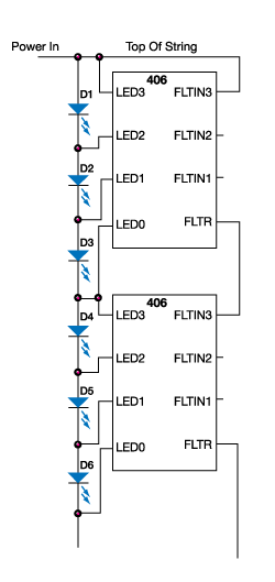
The most straightforward approach is to use locally powered circuits for detection, which in turn use a cascaded current signal as a fault indicator. Within the string, an IC solution can be designed such that the chip at the top of the string gets its fault current from the main LED power bus, and sends it’s on/off fault current indication to the chip below it in the string. At the bottom of the string the fault/no-fault current is put into a circuit that provides the final indication desired by the application. A cascaded multichannel example is shown in Fig. 1 , using the AAL406 LED Fault Monitor and Bypass Protection IC.

Fig. 1: The most straight-forward approach is to use locally powered circuits for detection, which in turn use a cascaded current signal as a fault indicator
One bad LED spoils the string
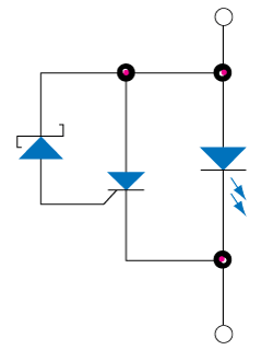
An open LED causing the loss of a whole string of LEDs within a fixture is a significant problem. One method of maintaining functionality of the string is to provide a bypass path around the open LED, allowing the rest of the string to continue operation. The simplest LED bypass is a two-pin SCR wired across the LED. As SCR gate trigger voltages are around 1V, too low to use directly, a zener is added to raise the trigger voltage (see Fig. 2 ).
If the LED opens, the voltage across it rises until the SCR gate voltage is reached and it fires, which then provides a latched path around the open LED. (LEDs use dc voltage and current, so they don’t need the added complexity of a TRIAC for bypass.) The SCR will stay active until the current drops below the SCR’s specified holding current. This is ideal for dc string current, which is the usual situation for LEDs. When there is PWM on/off dimming of the string, the SCR resets and refires each PWM cycle, thus not impacting functionality while also decreasing power dissipation.

Fig. 2: The simplest LED bypass is a two pin SCR wired across the LED. As SCR gate trigger voltages are around 1V, too low to use directly, a Zener is added to raise the trigger voltage
The stated approach has some limitations and requirements on the application to ensure proper operation. The LED string needs to be fed by something resembling a current source, where the LED voltage will rise if an open circuit occurs. Additionally, the voltage rise has to be greater than the trigger voltage of the bypass function. Also, the current path to the string should have some limit on instantaneous current, as SCRs fire quickly and LEDs present a relatively low load impedance. An example concern would be for failure of the SCR if it turns on to a large capacitance bus, with low resistance in its current path. Implementation of such a bypass and monitor solution in an IC can enable fault management of multiple SCRs by one package. The LED voltage, sensed for firing of the open LED bypass SCR, is also used to provide fault sensing of shorts or opens.
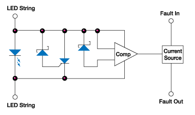
The IC-based cascaded current fault detection/reporting scheme described earlier is shown schematically in Fig. 3 . Note that one downside is that this approach will not integrate seamlessly with PWM dimming. When the string current is off/zero due to the PWM signal, the detection/reporting is in an ambiguous state, as the voltage/current across/through the LEDs is varying widely. An extra circuit at the bottom of the cascade could be used to use the PWM signal to latch the fault reporting while the LEDs are active/on, and to ignore/hold the fault status when the PWM signal is forcing the string current to zero.

Fig. 3: Shown is an IC-based cascaded current fault detection/reporting scheme
Thermal concerns
As with any electrical circuit, there are packaging and thermal issues to consider. Note the on-chip SCRs have an on-state voltage of about 1 V (positively correlated with current, negatively correlated with temperature). This means that, at 0.3-A current, they dissipate 0.3 W.
Getting the heat out into the ambient air is vital for reliability. Typical plastic IC packaging is not sufficient for the power levels described above. The IC packaging in this application requires measures to be taken for thermal management, without needing extraordinary measures. As a specific example, the AAL406 has three SCRs and fault sensing built into a surface-mount SOIC 8-pin package. The package’s thermal performance is excellent due to the exposed metal tab in the bottom, which is thermally coupled to the internal die. By putting a PCB copper pour underneath the chip, and soldering the tab to top-side copper, a large improvement in heat removal is realized.
Standard plated via holes should be used to connect the top-side copper to bottom-side copper beneath the IC to improve thermal transfer. In the worst-case condition, in the cases of multiple SCRs with higher-current loads, the thermal requirements can be more severe. In these instances, mounting them on a common sink, such as IMS (insulated metal substrate), is a likely solution. The extent of heat sinking required depends on the expectations of handling for failures versus repair, the handling of operating currents under normal operation versus occurrence of a failure, operating temperature range, cost considerations and other such system design and operating concerns. ■
References
1. AAL406 Datasheet (latest version available at www.asicadvantage.com).
2. AAL406 Demo Board Booklet.
Advertisement
Learn more about ASIC Advantage


