Developing a physical-layer test strategy for 100G
The demand for high-speed data interconnects creates difficult requirements demanding flexible, high-performance test solutions
BY HIROSHI GOTO
Anritsu, Richardson, TX
http://www.us.anritsu.com
The demand for faster data interconnects is resulting in extensive R&D into high-speed physical-layer circuits and devices. The inspection necessary to support device development and manufacturing requires measurement instruments that can both send and receive signals with various bit rates, levels and patterns. This highly flexible instrumentation must also be capable of detecting single-bit errors and measuring the total BER (bit error rate) in received signals.
Currently, the 100G market is divided into two segments. One is 100GE and the other is 100G DP-QPSK (long haul). Each has its own set of standard, as seen in the accompanying table, and both have their own test strategies that must comply with the requirements of the respective standard organizations.

Testing 100GE opto modules
Optical modules (CFP) used in a 100GE application must meet the IEEE specification. To verify that these devices are compliant, four 25.78G data streams of PRBS31 are required to measure BER (Bit Error Rate).
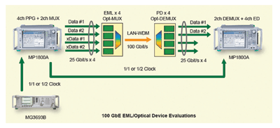
Using a test setp like that shown in Fig. 1 , The essential sensitivity test is executed by reducing the optical power to the receivers using optical attenuators. Engineers must make sure the test is free from errors at the minimum optical power which IEEE specifies to ensure device compliance.

Fig. 1. The diagram above shows an example test setup for an optical module BER test.
Testing in this application also requires a test-pattern generator (PPGs) to provide sufficient flexibility to identify any pathological pattern sensitivities. Tests with a high density of zeros, high density of ones, and inverse patterns are just a few common tests for pattern-dependent interactions. Transition errors, non-transition errors, code-insertion errors and code-omission errors are among the channel failure modes.
Measuring BER is also an important test for long-distance applications, such as those 20 km or longer. The test requires a 25.78G CDR (clock data recovery) because the incoming data signal to the receiver may not be synchronized to the clock from PPG. The CDR enables BER test of optical modules used for Metro Networks where the optical signal should reach 20km+ without any errors. The same sensitivity test as previously described should be made with this long reach test.
Jitter tolerance tests are also important. In real world networks, the traffic signals are distorted by chromatic dispersions, polarization mode dispersions, and X-talks. To secure the interoperability of the network systems, IEEE specifies the jitter tolerance of the optical modules. To test jitter tolerance, a certain amount of jitter should be added to the 25.78G data streams shown in Fig. 2 to measure the maximum jitter amount to which the system is tolerant for the error-free condition. The tester should have the capability to add enough jitter to the data to see how much jitter causes errors on the network component.
Testing 100G long haul
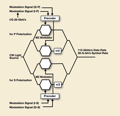
Test strategies for 100G long haul need to support devices that transmit and receive data using DP-QPSK (differential quadrature phase shift keying) modulation at a 100-Gbit/s rate. The equipment must be able to generate at least two but ideally four synchronized, programmable, 28-Gbit/s I&Q data streams (see Fig. 2 ). Similarly, 40-Gbit/s DQPSK modulation requires two synchronized 20-Gbit/s I&Q data streams. Testers with a pre-coding function to convert PRBS data stream for DPSK detection can drive the optical module directly without a precoder and make the evaluation easier and simpler.

Fig. 2. As this flow diagram shows, test equipment must generate at least two synchronized, programmable, 28-Gbit/s I&Q data streams.
In both applications, the test capability must include sufficient flexibility to allow test operators to experiment with bit patterns, and the modulation phase and frequency to determine the modulated channel’s margins. For example, the skew of I&Q signals should be independently changed over the wide range, such as 128UI, to measure the skew margin of the receivers.
An additional consideration in choosing test equipment for 28-Gbit/s BERT is the ability to change the photonic interface’s operating point. Some optical modulators drive better crossing at thresholds other than the 50% point. Testers should be able to adjust the crossing point of the nominal signal amplitude. By matching the drive signal to the optical modulator’s inherent characteristics, engineers can better determine a physical layer subsystem’s true performance schemes.
In these applications, engineers can measure optical modulator performance by using test instruments that generate DP-QPSK modulation signals. Instruments that produce pure PRBS31 signals without pattern length restrictions are also beneficial because they allow engineers to conduct highly reliable evaluations using high-load pseudo random patterns that closely emulate live traffic.
The ability to generate various patterns and true PRBSs is important, regardless of the speed because many standards require PRBSs that comply with ITU-T recommendations O.150 and O.151, such as PRBS23 or PRBS31. Some BERTs don’t comply with the ITU-T PRBS recommendations because they multiplex lower-bit-rate streams to create the higher bit rates. Such testers do not create true PRBS at the higher data rate if they perform this multiplexing improperly.
With increasing signaling rates, engineers implementing differential pairs on PCBs must confirm their layout with proven models before moving forward with board fabrication. Impedance mismatches give rise to reflections, ringing, and crosstalk. To ensure performance, engineers must be capable of margining the signals’ parametric behavior.
Pre-emphasizing test methods
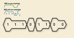
Pre-emphasis is a signal-conditioning technique in which a signal’s high-frequency content is accentuated prior to transmission through a medium (see Fig. 3 ). BERTs need to produce the best and squarest waveform with the least intrinsic jitter to conduct accurate pre-emphasis measurements. Generating test waveforms with low ringing and low intrinsic jitter is important to satisfy the IEEE requirements for jitter and ensure interoperability. The tester’s intrinsic jitter should be indistinguishable from the jitter of the DUT (device under test).

Fig. 3. Using pre-emphasis, a signal’s high-frequency content is accentuated prior to transmission to improve reception accuracy.
The ability to produce pre-emphasized signals with a fine degree of adjustability is also important. One method requires a single PPG module and a power splitter/combiner. The advantage is reduced cost but it is difficult to adjust phase using the delay line manually and the resultant signal is single ended.
A second method uses two synchronized PPG modules with a power splitter. PPG modules in this method need to vary the phase of its data output over a full UI (unit interval) in 1-mUI steps. When adjusting the data output amplitude on each PPG module and the relative phase between PPG modules’ data outputs, the multiple PPG modules can generate multilevel signals.
The third method uses the dual-channel capability of a 25/28G multiplexer unit that can be integrated into a BERT. This mux unit provides two independent high-speed signals from 8 to 28 Gbits/s. ■
Advertisement
Learn more about Anritsu


