By ROBIN JACKMAN
Field Applications Engineer
Tektronix
www.tek.com
Modern radar designs have evolved in parallel with improvements to range, resolution, and immunity to interference. This has allowed radar engineers to employ a wide variety of modulation techniques to improve overall system performance.
When measuring and testing a pulsed radar transmitter, it used to be that the signal you tested was likely to be a steady stream of pulses. Now radar designers are using a variety of techniques so that the equipment is able to transmit using the minimum power necessary, yet still receive the greatly attenuated return signals. These new techniques include pulse modulation and pulse compression, varying the pulse repetition interval (PRI) to eliminate range-gate blind spots, and using frequency chirped pulses or very narrow pulses with high bandwidth.
With evolved transmission techniques and designs comes the need for new sets of methods and equipment to characterize and troubleshoot dynamic modulation profiles. Designers need to test, measure, and analyze a much broader range of parameters than they did before. Modern signal-acquisition methods — such as segmented acquisition memory, streamed recording, and advanced triggering —all are needed to fully characterize a system.
Some radar transmitter measurements are more properly made in the time domain and others in the frequency domain, so both measurement domains are important. In the frequency domain, tests might include checking for out-of-band spurious emissions, which can be caused by many parts of a radar system, including DSP and control software. Spurious signals can also be caused by the hardware itself.
Commonly, spectrum measurements of the transmitted signal are characterized to help detect transients, memory effects, and mismatches within the transmitter chain. Also common are spectrum power measurements of the assigned channel and adjacent channels while in a frequency-agile operating mode. In the time domain, single-pulse testing is commonly used to reveal the quality of the individual pulses. In addition to pulse width and PRI measurements, measurements of rise and fall times are often needed, as well as analysis of errors in analog modulation (for example, FM modulation).
Many of today’s transmitter designs also call for complete pulse characterization. The measurements of multiple pulses may reveal differences between the individual pulses that can cause false or “blurred” radar readings.
One method of doing this involves a parametric trend analysis. Here, the technique is to parameterize the measurements so that all of the linear measurements can be made on a common pulse model. After this model has been determined, parameters for each pulse can then be measured. Statistics are then applied to calculate the variation of the entire ensemble of pulses. The pulse-to-pulse trend, histogram, and even frequency domain analysis (FFT results) can be applied to highlight potential problems in the radar system.
Speeding up pulse detection and analysis
Greater computational power is becoming ever more important because finding a pulse can be an algorithm-intensive process. This is especially true if the testing is performed over a wide amplitude range, as lower power pulses may have noise that can make it difficult to determine a pulse’s cardinal points.
Modern pulse analysis methods speed up the process of characterizing transmitter designs by taking advantage of the increased computational power of today’s test and measurement instruments, with their ability to quickly crunch the data for thousands of pulses.
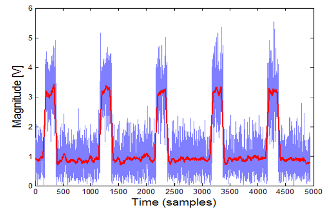
For example, one method applies four separate algorithms to pulse detection: moving average (Fig. 1) , magnitude histogram, local statistics, and least-squares carrier fit. Each of these algorithms is called within the DSP one at a time, the simplest and fastest first. If a pulse is found at any time, the process ends. This method ensures that the pulse is detected and its amplitude measured as accurately as possible — in the least amount of time.

Fig. 1: Modern pulse analysis methods speed up the process of pulse measurement by using powerful statistical algorithms such as the moving average, shown here as a red trace.
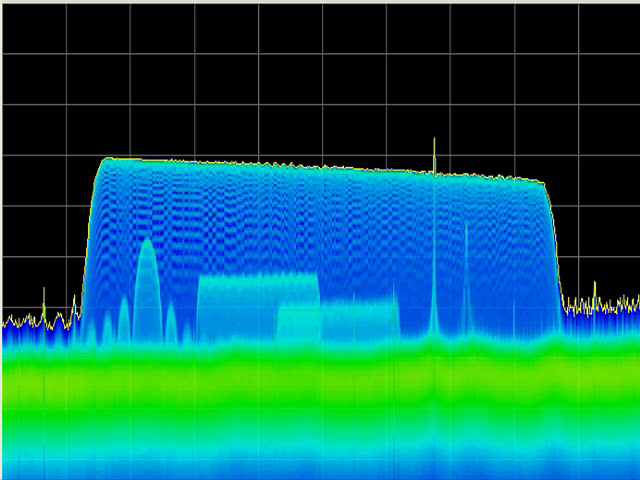
Rapidly changing signals require test instruments designed for real-time acquisition and processing. Real-time spectrum analysis tools have evolved over the past few years to be able to sample the incoming RF spectrum in the time domain and convert the information to the frequency domain using an FFT process. Spectral defects are best visualized using real-time displays that make it possible to observe infrequently occurring or low-power signals within other signals (Fig. 2) .

Fig. 2: Real-time visualization tools make it possible to observe infrequently occurring defects or low-power signals within other signals. Above, within the multi-GHz sweep, you can see a large LFM chirp pulse, as well as (from left) a lower-power CW pulse, two lower-power LFM chirps, and three other pulsed signals.
Troubleshooting a signal using advanced triggering
After a signal artifact has been detected visually, you can use triggering to isolate it for further analysis. For long signal acquisitions, triggering uses the acquisition memory more efficiently. This is especially true for pulsed RF signals, because the Off Time is rarely used — yet it almost always makes up a majority of the signal playback time.
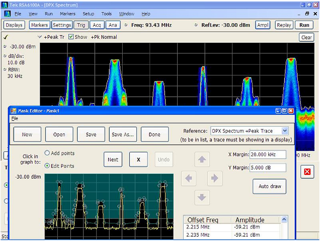
For more complex signal effects, the more trigger types available, the better. A frequency mask trigger (FMT) can act as a user-defined monitor for multiple frequencies (Fig. 3) . Time-qualified triggering provides a way to trigger on events of specific user-defined duration and, along with specific hold-off times, can help eliminate false triggering. Frequency edge triggers are useful because they can not only trigger real-time time-domain measurements but also synchronize all measurements with a single acquisition. Trigger input and output signals can synchronize multiple instances, including external instrumentation such as software monitors.

Fig. 3: A frequency mask trigger, shown here defined in the lower window, can act as a user-defined monitor for multiple frequencies.
Current real-time spectrum analyzer equipment and software place special emphasis on capturing “runt” pulses that often overlap in time and frequency with the desired signal, making them especially hard to trap and separate. An amplitude-qualified trigger can capture runt signals; they can also isolate pulses of specific amplitude and/or width within a pulse train.
Advertisement
Learn more about Tektronix


