BY MICHAEL JACKSON, Analog IC Design Engineer;
SEAN LONG, Director, Applications, Industrial & Healthcare Business Unit
Maxim Integrated Inc.
www.maximintegrated.com
Industry 4.0 is a new byword for the modern factory environment. It encompasses networked controllers continuously monitoring inputs from hundreds, or even thousands, of sensors like level detectors. Simultaneously, signals are sent to a similar number of output devices such as valves, solenoids, or motor drives.
In this article, we will show how electronic marshaling has simplified the process of connecting this expanding set of field wiring back to the controller. We will also present another solution that brings a new degree of flexibility compared to the electronic marshaling approach.
Wired marshaling
Until recently, the standard way of connecting field I/O devices to a programmable logic controller (PLC) has been through the traditional wired marshaling method, as illustrated in Fig. 1 . The multicore cables run wires from the field devices located on the factory floor to the terminal blocks of marshaling panels, usually located in an I/O room.
Here, the wiring is cross-marshaled so that each field device is connected to the I/O card of the appropriate controller channel.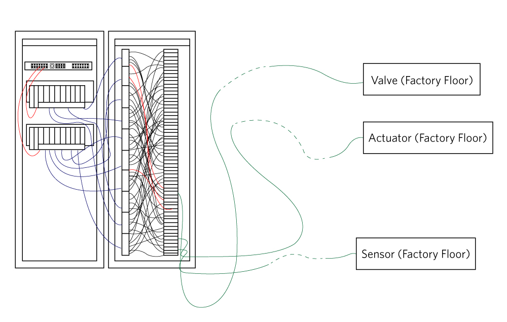 Fig. 1: A view of how wired marshaling connects field I/O devices to PLCs.
This approach has the potential to cause problems. For example, during cross-marshaling, it’s difficult to keep track of which wires are coming from and going to, leading to errors if wires are incorrectly connected or even left completely unconnected. Debugging and testing each connection can be time-consuming and laborious for technicians and engineers alike, potentially introducing costly delays to the commissioning of a new process.
In theory, once debugging is complete, the system should run correctly, but additional problems can emerge if unforeseen changes occur late in the project. Sometimes it may be necessary to add a new field device. For example, if a temperature switch is changed to a temperature transmitter, a digital input will need to be changed to an analog input.
An even worse situation occurs if new field devices are added to the system but the marshaling panel does not have enough spare connections of the required type to accommodate them. In this case, the controller would need to be replaced, potentially adding additional cost and delay to the project.
Electronic marshaling
Wired marshaling has started to be replaced by electronic marshaling, a new approach to signal routing in process automation (Fig. 2 ).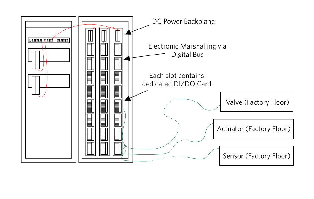 Fig. 2: This is how electronic marshaling improves signal routing in industrial automation designs.
This technique was developed to prevent the human errors associated with the manual element of wired marshaling, namely the cross-connection of the I/O devices on the marshaling panels. As with wired marshaling, the multicore cables from the field are routed to the right side of the terminal blocks in the marshaling cabinet by technicians on the factory floor.
However, in the I/O room, there’s no longer any need to manually connect each terminal block to the appropriate controller I/O channel, as this is handled electronically within the system itself. The clear advantage of electronic marshaling is that an I/O device can be connected to a specific controller whenever necessary without physical wiring changes.
If at a later stage in the project, changes are made to I/O types, or additional devices are required, no changes are needed to the existing wiring or cabinets. In addition, extra I/O capacity can be added to the marshaling cabinets and then electronically marshaled to the controllers as required.
At the heart of the electronic marshaling approach is a rack of portable and replaceable modules or cards. An appropriate card type is inserted into the slot to which the wiring for an I/O field device is connected. For example, a digital input (DI) card would be placed in the slot for a temperature switch.
The card would then connect to the appropriate channel of the controller. The function of each controller channel is defined by the type of card placed in each slot.
A new type of digital I/O
While the flexibility offered by electronic marshaling is obvious, there is a not-so-obvious inherent inflexibility. Traditionally, industrial and process control engineers have used the term “digital I/O” to refer to digital signals transmitted and received by PLCs. However, the term itself is something of a misnomer. There is no such thing as a “digital I/O” channel on a PLC.
There exists either a digital input (DI) channel or a digital output (DO) channel. Thus, if it’s necessary to change the functionality of a controller channel from a DI to a DO, or vice versa, the physical card for the channel must be changed. Also, the total number of DI and DO channels is defined by the number of each type of card in the rack.
That places limitations on the flexibility of the electronically marshaled system by fixing the number of DI channels and DO channels in the rack. Clearly, a more desirable scenario would be to configure each channel as either a DI or a DO, as needed.
It’s now possible with a high-side push-pull driver that operates as both an industrial DO and industrial DI. Using the MAX14914 from Maxim Integrated, for example, the PLC can configure each card to function as either a DI or a DO.
A card doesn’t need to be manually removed and reconfigured if the functionality of the channel changes. Control channels can truly be designated as “digital I/O” channels without limiting the number of each type of channel. The only limitation will be the number of channels the PLC itself can handle.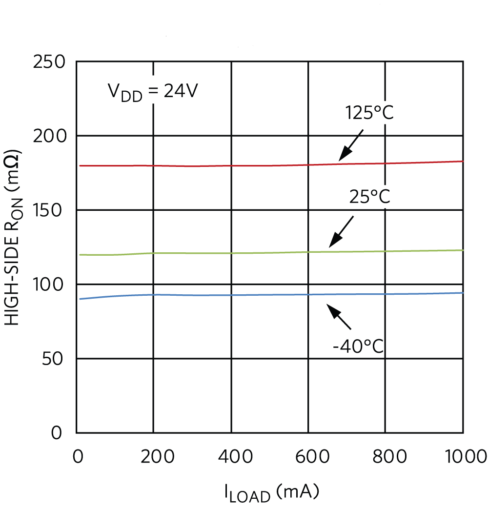 Fig. 3: High-side on-resistance vs. load current in a high-side/push-pull driver.
Other important features of a high-side switch like MAX14914 include low RON (Fig. 3 ) and very low propagation delay of less than 2 µs in DI mode (Fig. 4 ). Fig. 4: Propagation delay vs. temperature in DI mode.
Conclusion
In this article, we reviewed the traditional approach to signal routing in process automation systems, namely wired marshaling. We showed how the problems associated with this approach have been largely addressed by the migration to electronic marshaling.
While this has been a considerable improvement in its current guise, it’s not without its limitations. A high-side switch with digital input configuration, such as the MAX14914 chip, offers a new degree of flexibility for electronic marshaling.
The ability to electronically configure an individual controller channel as either a digital input or digital output, without the need to change hardware and without limitation on the available card types, allows greater design flexibility and reduces the costs associated with changes that can occur during the project commissioning process.
Advertisement
Learn more about Maxim Integrated


