By T.K. Hareendran, contributing writer
My first foray into the IoT utilized the Espressif ESP8266, an SoC with 32-bit MCU and 2.4-GHz Wi-Fi built in. Since then, I have used many different module variants based on the microcontroller. So when its more powerful sibling, the ESP32, landed on my ground, I had to have a go at trying it.
The Espressif ESP32 is a promising Wi-Fi- and Bluetooth-enabled SoC with a massive GPIO count. Recently, I purchased (on eBay) two generic ESP32 development boards for some experiments. Each is powered by the Expressif ESP-WROOM-32 Wi-Fi and Bluetooth module, which contains the ESP32 SoC, flash memory, and chip antenna. Espressif offers several development modules/boards to help users evaluate ESP32 chip functionality, and the ESP-Wroom-32 is the smallest module intended for installation in end-user products.
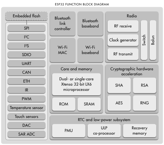
Fig. 1: The ESP32 SoC integrates dual CPU cores and a peripheral co-processor along with Bluetooth and Wi-Fi radio elements. (Source: Expressif)
ESP-WROOM-32
According to the datasheet, the ESP-WROOM-32 is a powerful, 38-pin Wi-Fi/Bluetooth/BLE MCU module that uses the scalable and adaptive ESP32-D0WDQ6 chip. This chip contains two low-power Xtensa 32-bit LX6 microprocessors at its core along with an ultra-low power (ULP) co-processor. The two CPU cores can be individually controlled, and their clock frequency is adjustable from 80 MHz to 240 MHz. The user can also power off the CPUs and make use of the ULP co-processor to handle A/D conversions and monitor peripherals for changes in value or crossing of thresholds.
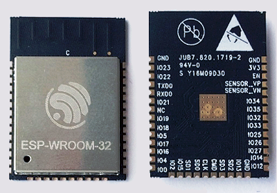
Fig. 2: The ESP-Wroom-32 module.
The integration of Bluetooth, Bluetooth LE, and Wi-Fi ensures that the module can target a wide range of applications. The Wi-Fi allows a large physical range and direct connection to the internet through a Wi-Fi router, while Bluetooth permits the user to conveniently connect to the phone or broadcast low-energy beacons for its detection. The ESP32’s negligible sleep current ESP32 (less than 5 μA) makes it suitable for most battery-powered and wearable electronics applications.
The items that I got from eBay, described as “ESP32 development Boards,” are actually just small and convenient breakout boards based on ESP-WROOM-32 modules, with a few additional components. These breakout boards expose the module’s I/O through male headers, and feature SiLab’s CP2102 chip for Serial-to-USB debugging via a micro-USB port. The USB-to-Serial programming interface also provides the power supply for the board. There are onboard 3.3-V regulator chip, buttons, and LEDs, as well.
Both boards offer near-similar capabilities but with different pinout configurations. The first one, often called a DevKitC, has a 38-pin (2 x 19) layout and measures 55 x 29 x 14 mm. The second one, sometimes referred to as a DOIT board, has a 30-pin (2 x 15) layout and measures 52 x 29 x 14 mm.
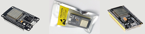
Fig. 3: The development modules that I acquired from eBay.
I opted for these easy-to-use ESP32 development boards even though they are, relatively, a bit pricey (at least two times the cost of the module alone). If you’re going to integrate the ESP-WROOM-32 module in a (commercial) project, you can use it without any additional stuff. But for prototyping and use with breadboards, you most likely will need a special breakout board/testbed like these to expose the GPIOs. The module’s castellated mounting holes mean that the requisite soldering work to connect the I/O is not easy. Trying to use the bare module may, thus, be a trouble for many, and possibly a funny experience for a few. The boards are much more convenient.
A bumpy takeoff
Getting started with the boards was quick. Because I had already installed USB-to-Serial converter drivers (VCP drivers) in my PC, I could simply connect a micro-USB-to-USB cable between the board and my computer. I could immediately see that Windows assigned a unique port identifier for the board.
Because the official ESP32 website mentions Arduino, I decided to play with the Arduino core for ESP32 chip released by Espressif. This software explains how to make the ESP32 work with the Arduino IDE. Unfortunately, it was not a smooth sailing. First, the directions provided were both somewhat pitiful and intimidating (admittedly, everything is still preliminary right now). Second, the ESP32 core is Xtensa-based, not the familiar ARM/AVR. So they don’t have an Arduino board manager install option yet. After some initial troubles and discombobulations, however, I managed to make everything work but failed to record my steps in detail for the sake of newbies. (Sorry.)
The process (tested on 64-bit Windows), in a nutshell, was this:
- Make sure you keep your latest version of Arduino IDE handy
- Install the Git GUI
- Start Git GUI and select Clone Existing Repository
- Select source (https://github.com/espressif/arduino-esp32.git) and destination (your target directory) and click Clone to start cloning the repository
- Go to the destination folder, open Tools (…/Arduino/hardware/espressif/esp32/tools ), and double-click get.exe
- When get.exe finishes, you should see all requisite files in the named directory
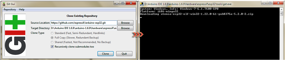
Fig. 4: Cloning the Git ESP32 repository.
Next, plug the ESP32 board into your computer’s USB port and wait for the drivers to install. Thereafter, run the Arduino IDE, select your board, and select the COM port. Finally, compile and upload your code.
For my maiden test, I selected GetCHIPID sample, as it simply retrieves the Chip ID (actually the MAC Address) from the board. I could upload the code, and it, indeed, returned my Chip ID — BC7306A4AE30. A short test flight, but a successful one!
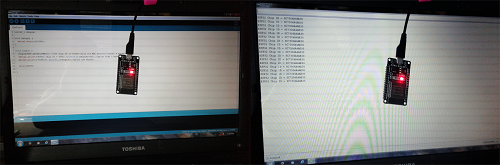
Fig. 5: A successful maiden test retrieved the chip’s ID code.
Wrapping up
The ESP32 is an extremely powerful IoT-enabled microcontroller, and using an ESP32 development board exposes this power in a very pleasurable board design, suitable for both beginners and advanced users. Most of the cheap ’n’ cheerful ESP32 development boards are powered by ESP-Wroom-32 modules, one of the great choices for IoT applications nowadays. The ESP32 is meant to be used in beating wireless applications (Wi-Fi or BLE projects), but its powerful features aren’t fully functional with the Arduino platform on most of the development boards right now. That’s the only drawback I noticed, though.
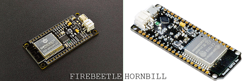
Fig. 6: Fully Arduino-compatible ESP32 development boards.
That said, Arduino fans (even novices) looking for an easy-to-go ESP-Wroom-32 platform that enables rapid prototyping using Arduino can try the “FireBeetle” from DFRobot (not FCC-certified). Another nifty addition here is the “Hornbill” from “Explore Embedded” — India. Both claim complete compatibility with the Arduino IDE.
Advertisement
Learn more about Electronic Products Magazine