Christmas is more or less considered a festive holiday, and like all festive holidays, is an excellent opportunity to harness your electrical know-how to build cool stuff for the sake of building cool stuff. That’s part of the fun in being an electrical engineer or hobbyist; devising and implementing unique solutions.
The holiday is practically smothered in electronics, ensuring there are sufficient niches from which to inspire a project. The three examined in this piece are the LED ornament, the Christmas light controller, and an Internet-connected Christmas tree that lights up when you’ve received an email.

LED Ornament
The LED ornament displays the message “MERRY CHRISTMAS,” across its eight by eight LED arrangement while hanging on a tree.
To get started on the project, procure the following items:
– 1 x PIC16f677 microcontroller (SMD)
– 1 x 8×8 bi-colour LED matrix
– 1 x coin cell battery holder
– 1 x PCB
– 2 x coin cell batteries
– 2 x 10k ohm resistors (SMD)
– 2 x mini push buttons
– 1 x mini slide switch (SMD)
– pickit 2 (or similar programmer)
– Soldering Iron (with a small tip)
– Solder
– Solder wick (optional)
– Flux (optional)
Step 1
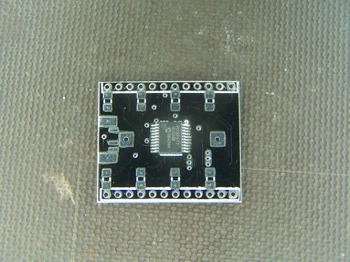
Begin by downloading the PCB board layout to create your own PCB with the appropriate circuit tracks. Once the board is clean and ready, solder on the MCU; apply flux to achieve a smoother finish. Apply solder to the top and bottom left pads and line up the MCU with the pads.
Step 2
Connect a Pickit programmer, or whatever PIC microcontroller programmer you prefer, using a five pin header. If you opt for another PIC programmer, then just install the PickIt software on your computer as this will come in handy for loading the Merry_Christmas.HEX, the file that controls the LEDS, onto the board.
Step 3
Next, solder in the shorting links to the MCU. Shorting links are preferred over SMD resistors due to the 3 V low voltage that’s needed to power the project. The LEDs drop the majority of the 3 volts. Anything residual is picked up by the microcontroller. Any additional external resistance will result in a dim display. If your power source exceeds three volts, then 100 to 150 ohm resistors are a necessity.
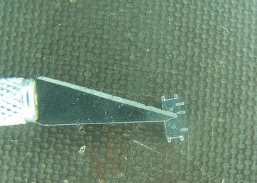
After you’ve finished soldering the links, it’s time to solder the slide switch to MCU as well. The switch contains two plastic tabs beneath it that must be removed to prevent the switch from sticking off the circuit. Use a bit of extra solder to firmly secure it.
Step 4
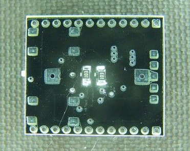
Solder the two surface mount 10k ohm resistors in the center of the board as displayed below.
Step 5
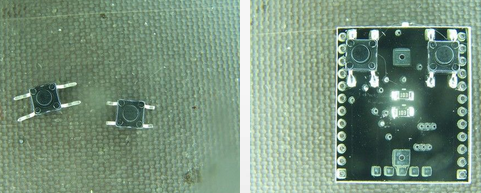
Take the push-able buttons and flatten out the leads by spreading them apart. Cut off any excess lead by measuring how much material sticks out from the button’s designated position on the board. The buttons can now be soldered on.
Step 6
Use the image below as a guideline for soldering the battery holder in the central position on the board; the opposite side fits snuggly between the two buttons.

Now it’s finally time to solder in the 8×8 LED grid matrix. The LEDs have both a green and red cathode that’s activated depending on how you solder the matrix to the PCB. The green diodes are activated by default if no modifications are made. To install the matrix in this manner, line up the legs of the display with the PCB and push them all the way through and solder. There’s no need to bend anything.
Configuring the red display requires that we bend the eight prongs that connect to the green cathode, in order to hinder this connection. Use the picture below as a reference.
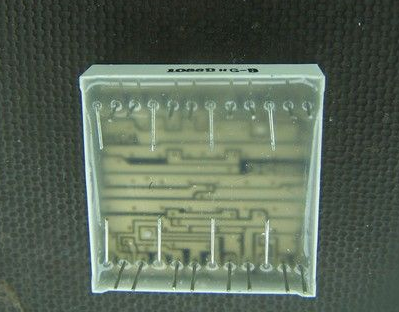
Once this is completed, we simply align the remaining prongs with the corresponding holes in the PCB while assuring that the text points up and the battery holder is to the right. Solder the legs to the board when finished.
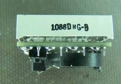
Step 7
Turning the device on is simply a matter of flicking the switch. Once activated, the message “Merry Christmas,” scrolls across the LED matrix until device is deactivated (the same way it is turned on) or the battery runs out.
Project via user Bradsproject from Instructables
Christmas light controller
Plugging in Christmas lights and leaving them on for hours to consume tons of electricity is something your peasant neighbors do. But you’re not simply one of the common folk. No, your curiosity and ingenuity have turned you into a “Maker,” and as a maker, you will strive to think of creative solutions that establish a more convenient life for yourself. Or maybe you just like building things. Regardless, Zedomax’s Christmas light controller project takes five minutes to set up once all the materials are collected, and uses a programmable logic controller to customize your Christmas lights.
The essential parts are:
– 1x CuSB22R from cubloc.com
– 1x AC power cord
– 3x AC Connectors from Home Depot (More may be needed depending on the number of Christmas lights you wish to control.)
– Bunch of wires
Step 1
Cut off the AC power cord to reveal three wires: a green, black, and white one. Splice them and connect the green wire to the “FG” label on the CuSB. This is the frame ground that prevents your house from catching fire.
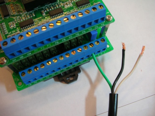
Step 2
Place the black and white wires on the terminal headers; place the black wire on the N and white on the L.
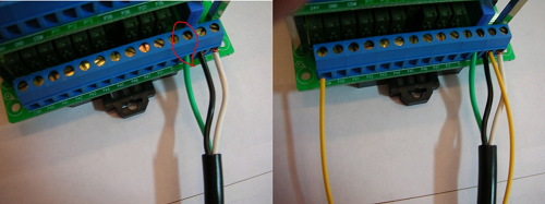
Once this is completed, join a wire between the CUSB label COM and the N label. Next, firmly fix another wire from the P40 label on the CUSB to one of the two screws on the AC connectors. Polarity doesn’t matter.
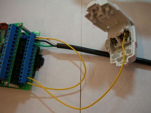
Step 3
Repeat this process for the remaining AC connectors, running one wire from the CUSB label P41 and a second from P42.
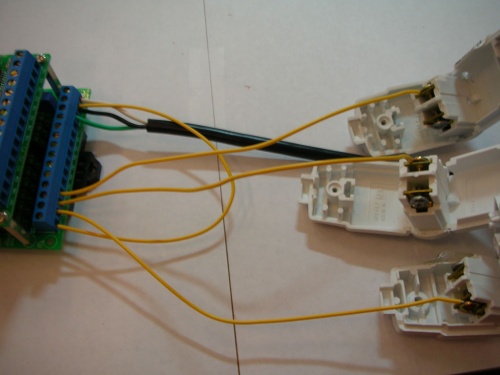
Step 4
From the CUSB label L, where the white wire is connected, draw three more wires to the remaining AC connectors.
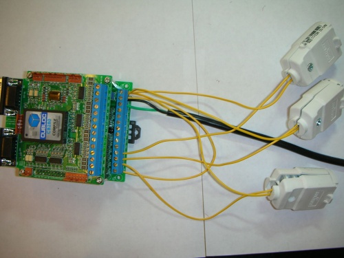
Step 5
Now it’s time to add the magic – begin joining the AC connectors with various Christmas lights. Afterwards, attach the serial cable to a computer to begin programming the unit. Install the CublocStudio software needed to program the CUSB and copy and paste the code between the //.
//Const Device = CB280
Dim Interval As Long
Interval=300
Do
High 40
Low 41
High 42
Wait Interval
Low 40
High 41
Low 42
Wait Interval
If Interval>100 Then
Interval=Interval-50
Elseif Interval>0 Then
Interval=Interval-10
Else
Interval=300
End If
Loop
//
The interval of 300 is modifiable to suit blinking needs.
Project via Max @ Zedomax
Internet-connected Christmas tree lights up when you’ve received an email
Getting swamped with emails is almost a guarantee this holiday season thanks to zealous marketing campaigns, company year end and overly excited acquaintances wanting to share the holiday spirit. If you need a little help managing this flow of information, the email-light-up-Christmas-tree project is the perfect way to remind you to clear out your inbox without being tied to a phone. Best of all, the project is very easy to complete, requiring a few outside components.
These components include the Arduino + Wi-Fi/Ethernet shield and a PowerSwitch tail accessory. (These can all be picked up at MakerShed.) PowerSwitch Tail allows you to safety control a device plugged into a 120vac outlet using almost any MCU.
Step 1
Begin the project by interfacing the Arduino and its respective shield. Afterwards, you will need to strip a wire to form a connection between the PowerSwitch Tail and the Arduino’s ground and a digital pin, that’s extended through the Ethernet Shield.
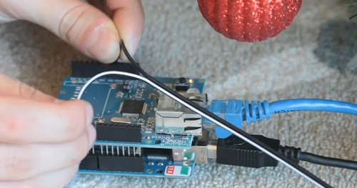
Anytime that pin is brought high, the relay inside the PowerSwitch Tail closes the circuit between the wall outlet and the Christmas lights on your tree.

Step 2
Programming the Arduino for this task is relatively simple in and of itself, thanks to the integration of DNS and DHCP capabilities coupled with improvements in the code library. The necessary code to get you started can be downloaded from Make magazine; it will need to be tweaked to access the URL of your email web server using a PHP scrip that checks for new emails over IMAP. Once the script determines a new email has been sent, it will activate PowerSwitch Tail’s relay switch and provide power to the Christmas lights.
The underlying concept of this project is applicable to all kinds of A/C devices thanks to the Arduino , Ethernet Shield, and PowerSwitch Tail combo. This means that it’s possible to infuse many other household objects with the power of the Internet-of-Things as the Arduino controls the Tail, and the Tail controls the power relay.
Project Via Matt Richardson @ MakeMagazine
Advertisement
Learn more about Digi-Key


