Economically generating vector microwave signals
Quality vector-modulated signals for receiver testing may be generated easily using test equipment already found in many labs
BY JUSTIN STALLINGS
Rohde & Schwarz, Columbia, MD
http://www.rohde-schwarz.com
Vector modulation is increasingly used in microwave and satellite communication applications, but generating vector-modulated signals for measurement can be difficult and expensive. However, using readily available test equipment found in many labs, it is easy to generate these signals if you know what to watch for.
Perhaps the most cost-effective method, without sacrificing performance, is to use an I/Q mixer to modulate a baseband generator’s I/Q signal on to a local oscillator’s (LO) carrier frequency. This method may produce vector-modulated microwave signals with very good modulation accuracy and clean spectrum.
Since I/Q mixers work directly with baseband signals, a baseband generator rather than a higher-cost vector RF or microwave signal generator may be used to supply the I/Q input signals (see Fig. 1 ). This significantly reduces cost, because there is no need for RF hardware to generate an I/Q signal.
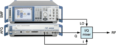
Fig. 1. A sample test setup uses an I/Q mixer, a baseband generator as I/Q modulation source, and a microwave signal generator as LO source.
Fundamentals
Those familiar with mixing fundamentals likely know that the frequency of the signal to be modulated is called the intermediate frequency, or fIF . We refer to the frequency of the mixer’s local-oscillator (LO) input as fLO . As with conventional RF mixers (those using an RF signal generator’s output as modulation signal), the spectrum at the output of the I/Q mixer consists of the following components:
The desired signal at the sum frequency, fLO + fIF. The unwanted mixing sideband at the difference frequency, fLO − fIF. Unwanted higher-order mixing sidebands, such as fLO − 3fIF , fLO − 2fIF , fLO + 2fIF , fLO + 3fIF ..Unwanted leakage from the LO.
Filtering these unwanted signals is not required, because I/Q mixers inherently suppress the LO carrier (leakage) and mixing sidebands by about 30 to 40 dB on average.
The difference between I/Q mixers and RF mixers is that the IF for an I/Q mixer is a dc signal (fIF = 0). Thus, the entire output spectrum described above is at the same frequency, equal to the LO frequency. Whereas this means the out-of-band spectral performance is better than with RF mixers, the modulation quality as measured in-band is much worse. That is, unless you choose a baseband generator capable of compensating for the undesirable modulation effects inherent in using I/Q mixers.
Optimizing signal quality
Error vector magnitude (EVM) is the most comprehensive way to evaluate modulation quality, so we will use this entity to monitor our results. Since EVM is measured within the desired bandwidth of the microwave vector-modulated signal, one would expect worse EVM using an I/Q mixer rather than an RF mixer, because all output spectral components (wanted and unwanted) are located in band.
As an example, we use the test setup shown in Fig. 1 to generate a 16-QAM, 1-Msymbol/s signal at 22 GHz. The resultant spectrum is free of out-of-band components, but the EVM is a rather poor 4.6%. Our goal is to improve this value and approach the typical performance of an RF mixer, where the LO leakage and unwanted mixing sidebands are out of band (hence, not affecting EVM).
Adding a frequency offset in the baseband generator will produce a non-zero IF, simulating the output spectrum of an RF mixer (see Fig. 2 ). The result with 20-MHz frequency offset is an EVM measurement of 0.45%, or one order of magnitude better performance. We wish to approach this value without the baseband frequency offset.
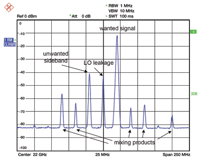
Fig. 2. The I/Q mixer output spectrum for 16-QAM signal with 20-MHz baseband frequency offset is similar to an RF mixer output with a 20-MHz IF input.
There are three ways we may improve EVM performance:
Compensating for I/Q phase mismatches.Compensating for I/Q gain mismatches.Varying the LO power.
The first two may be accomplished using a baseband generator capable of adding I/Q impairments, while the third is possible with any LO source capable of varying its output power.
In our example, adding an I/Q phase error of −4.0 results in a mixing sideband rejected by an additional 11.5 dB (see Fig. 3 ).
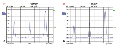
Fig. 3. The I/Q mixer output spectrum shows mixing sideband rejection (a) without I/Q phase error compensation and (b) with I/Q phase error compensation.
The desired I/Q phase error may be determined by varying the applied phase difference and monitoring this effect on sideband suppression. Alternatively, you can connect a vector signal analyzer, measure the quadrature (phase) error and compensate for it in the baseband generator. The EVM with I/Q phase error compensation (and 20-MHz offset removed) is 2.0%, compared to 4.6% without.
Increasing rejection
Further rejection of the mixing sideband is possible by adding a suitable gain imbalance to compensate for the I/Q gain mismatches. In our case, the best improvement in sideband rejection is another 12.3 dB using a gain imbalance of 0.3 dB in the baseband generator. Again, the desired gain imbalance can be found manually or by measuring this parameter with a vector signal analyzer.
In total, we have now improved mixing sideband rejection by 23.8 dB (see Fig. 4 ). The resultant EVM with I/Q phase and gain mismatch compensation is 0.6% much nearer our 0.45% goal.
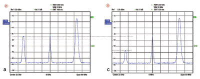
Fig. 4. This I/Q mixer output spectrum shows mixing sideband rejection (a) with I/Q phase error compensation only and (c) with both I/Q phase error and I/Q gain imbalance compensation.
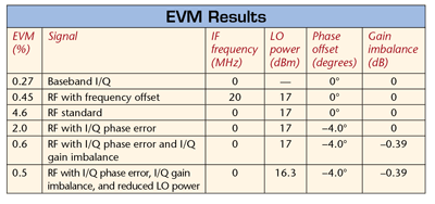
Varying the LO power can fine-tune modulation quality. We started with LO output power equal to 17 dBm as specified in the I/Q mixer datasheet, but will this yield our best result? As it turns out for us, increasing the LO power degrades EVM performance, while reducing it slightly will improve the EVM. In our example, reducing the LO power from 17 to 16.3 dBm results in optimal EVM performance of 0.5%, which closely approaches our goal of 0.45% (see table ). We’ve achieved the desired performance using an I/Q mixer instead of a higher-cost vector signal generator. ■
Advertisement
Learn more about Rohde & Schwarz


