By RAJ RADJASSAMY, Senior Product Manager,
GE’s Critical Power solutions,
www.geindustrial.com/products/critical-power
Fighting the inherent byproduct of ac-to-dc power conversion — heat — has always been a challenge for electronics design engineers. Today, that issue has grown exponentially with the seemingly contrary requirements for more power in smaller printed circuit board (PCB) or electronic device packages.
Higher demands for more computational capacity, with a requisite power increase, puts a disproportionate stress on power supplies. A doubling of load current actually quadruples the power loss (I2 R) of a power supply unit (PSU), increasing thermal output and the demand for more effective cooling solutions.
Figure 1 shows that the efficiency of a PSU increases as its output load rises, but only up to a certain point. After that, a higher output load will decrease the PSU’s efficiency due to power losses. Decreased output power efficiency means more heat needs to be dissipated from the PSU, which in turn must be removed by some cooling mechanism. The cost of thermal management has become so great that in some applications, such as a one unit (1U)-high data center server cabinet, the annual cost of cooling a server is approaching its procurement cost.1
Fig. 1: The efficiency of a PSU increases as its output load rises, but only up to a certain point.
Electronics designers have three basic power conversion cooling methods in their “cooling toolkit”: active forced-air convection, passive natural convection, and passive conduction.
Active forced-air convection
Traditionally many applications use active forced-air convection, with a fan directing airflow onto the hot surfaces of a PSU to remove heat via air convection. Using fans for direct airflow cooling makes sense in many applications where component density isn’t an issue or when a device’s enclosure has enough room for adequate airflow. In many newer high-density applications, however, active cooling with fans presents many challenges.
First, cooling fans use valuable board or device real estate needed for many of today’s high-density, higher-power designs. Adding a mechanical element, such as fan, also increases system reliability because fans contribute to lower mean time between failure performance, boosting both system failure rates and raising maintenance costs. In outdoor applications, dust accumulation and harsh operating conditions also can considerably limit a fan’s reliability.
Further, in some applications — such as hospital settings and using medical equipment — the noise generated by a constantly whirring fan motor is unacceptable for patients and staff. In scientific and research laboratories where highly precise measurements are collected, fans create vibration and noise from their mechanical parts that can interfere with the lab’s precision measurement equipment. Fan speed control techniques that actively slow down the fan under conditions of lower output power and/or lower ambient temperatures can help in such situations.
Passive convection
In lieu of a fan, passive natural convection cooling using an open-air rack to promote the natural movement of air across electronic components can sometimes adequately remove excess heat from a PSU. Passive refers to the absence of fans or other mechanical means to facilitate the movement of air.
Another approach to convection cooling is an ionic wind cooling system. In this method, increased airflow is generated based on the principle that air moves between two charged electrodes. The advantage of an ionic wind system over fan-based convection cooling systems is that an ionic wind system has no moving parts to wear out.
Passive conduction
For applications where fans are not feasible or passive convection can’t dissipate heat adequately, conduction cooling is a strong option.
Conduction cooling, which is sometimes referred to as fanless cooling, dissipates heat by placing the PSU in direct contact with heat sinks, cold plates or other similar thermal transfer approaches. In this configuration, the heat is conducted through the colder material and away from the PSU or other electronic components. The removal medium employed in a conduction cooling subsystem can be air, water, oil, metal or special liquids.
Some specific examples of fanless conduction cooling involve placing a PSU or other electronic component in direct contact with one of the following conductive media:
Heat Sink : A heat sink consists of a metal attachment which is connected to the PSU or other component to conduct the heat away from its source. Once the heat is transferred to the heat sink by conduction, it can be removed through natural air convection or other means. When designing this kind of thermal management system, an engineer must ensure that the heat sink is in contact with the PSU. Heat sinks, while simple, can take up valuable physical space that might be better used for other purposes, while also adding weight to the power supply.
Heat Pipe: The basic heat pipe consists of a pipe with a circulating liquid. One end of the pipe is in contact with the hot surface. The liquid in the pipe vaporizes from the heat being dissipated by the PSU. When the vaporized liquid encounters the cooler surface in the pipe, it condenses back into its liquid state and recirculates through the cooling system. Heat pipes can be effective in carrying heat away from the heat source to a heat-transfer mechanism, yet designers need to cope with the additional space requirements and the potential for leaks damaging the electronics.
Cold Plate: A cold plate relies on a fluid, either water or some other refrigerant, to remove heat. Typically, the cold plate has small pipes in metal casings embedded beneath the surface of the plate. When the refrigerant liquid moves through these pipes, they remove heat from the surface that the plate is in contact with. Again, the extra space required for this method of cooling can be a consideration along with compensating for potential water condensation.
Submersion Liquid Cooling: With this sort of cooling system, the PSU or the entire system is submerged in an electrically inert fluid. Submersion liquid cooling systems provide excellent convection properties and protect electronic components from humidity and water damage. Its benefits, however, often are outweighed by the cost of special tubing, cooling liquids and immersion mechanisms.
Designing in the negative space
Using various heat transfer, or conductive, methods to manage PSU heat challenges also opens up new ways for power supply designers to think about size, packaging and placement options for power conversion. The goal here is to find unused or “negative” space to place power units closer to conductive cooling elements such as heat sinks.
In one example of an open-frame power supply, we first looked at ways to reduce the size of the magnetics by deploying zero-voltage switching, quasi-resonant topology at high switching frequency. We also located heat-intensive integrated circuits (IC) on the bottom of the PCB — which was previously unused space — to better employ conductive cooling. This approach not only eliminated the need for a fan (see Fig. 2 ), but also reduced the comparable power module size from 21 cubic inches to 11.2 cubic inches while providing the same 200 watts of output.
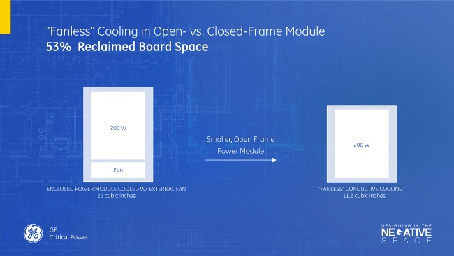
Fig. 2: Example of how to reduce the size of the magnetics by deploying zero-voltage switching, quasi-resonant topology at high-switching frequency.
Another example of looking for ways to harness conductive cooling involves flipping the power supply module on “its head,” slimming the profile height from 12 mm to just under 3 mm (see Fig. 3 ). Placing the power module directly next to conductive heat elements pulls away heat, while the under-board placement frees up space on the top of the PCB for higher computing density.
Fig. 3: Conductive cooling involves flipping the power supply module on its head, slimming the profile height from 12 mm to just under 3 mm.
In both of these examples, critical space is given back to designers to harness improved processing capacity, while also managing thermal dissipation.
As new thermal management solutions evolve — be they active or passive convection or newer conduction methods — each approach will spur power-design teams toward higher power efficacy, better component density and stronger computing capacity.
For a white paper on “Conductive-Cooled Fanless Power Supply Units,” click here.
Click here for an introductory video on Designing in the Negative Space.
References:
- Electronics Cooling, Feb. 1, 2007, “In the data center, power and cooling costs more than the IT equipment it supports,” http://www.electronics-cooling.com/2007/02/in-the-data-center-power-andcooling-costs-more-than-theit-equipment-it-supports/
Advertisement
Learn more about GE Critical Power


