BY LORENZO CIVIDINO
Director, Global Applications and Support;
HAI HO, Technical Applications Support Engineer
SL Power Electronics
www.slpower.com
When selecting a power supply, one of the most important functional requirements of the product is its EMI performance. AC/DC power supplies are the interface between the end-product electronics and the power utility providing the energy to power the end application. FCC and International Standards require product EMI performance to comply with the emission limits defined in the standards depending on the application.
A common assumption is that EMI emissions are highest at full-load conditions or at a certain AC line voltage range. However, depending on the power conversion topology of the power supply, the emissions can vary significantly over line voltage and over its load range. This article discusses considerations when performing verification tests and provides data showing significant EMI performance variations over load ranges. In some cases, low load can be significantly worse than full load. Recommendations are made on the load and line conditions to perform the verification testing. These recommendations ensure proper and thorough evaluation while also minimizing the tests required to achieve a high confidence level of compliance.
The endless pursuit for higher efficiency is driven by customers’ desires for smaller, lower-cost power supplies. In addition, government regulations (DoE Level VI, EU ErP, etc.) are mandating higher-efficiency adapters, which have motivated the industry to find innovative solutions to meet these requirements. For these reasons, novel solutions have surfaced with some unintended consequences to EMI performance.
External power supplies use variable modes of operation to reduce no-load power and achieve high efficiency. For example, as the output load decreased, the converter may switch to a burst mode of operation in order to minimize power consumption. This can result in resonance of the EMI filter and cause an increase in the conducted emissions at these lower loads compared to higher-load conditions. This situation may be overlooked if there is an assumption that conducted emissions are worse at full-load conditions.
Higher-power converters (~80+ W), especially those needing to meet class C or D harmonic current, will have a power factor correction (PFC) stage to minimize input current harmonics. There are various methods of achieving the PFC. These include transition mode control, two-phase PFC stage — in which one phase may be disabled at lower loads, then enabled and phase-shifted to reduce input ripple current at higher loads — and fixed and variable frequency modes, to name a few. All these techniques offer advantages in reducing power losses over a wide AC mains variation and wide load variation. However, they also pose a challenge in designing an EMI filter that will be effective at heavy and low loads with less damping. To compound the matter, system-level EMI filters are often added by system design engineers to address EMI sources generated by the system electronics that may be powered by the AC/DC power supply. In many cases, the added system-level EMI filter can make matters worse due to the impedance mismatch of the system EMI filter and the AC/DC power supply EMI filter.
To illustrate the issue, the following are some actual examples:
A common technique uses a variable switching frequency to reduce power loss across line voltage and load current, also the burst mode/phase management (pulse skipping or turning off one phase at light load), which is extremely useful to meet light load efficiency standards. These operating conditions have changed the way we look at the conducted emissions.
Case Study #1: Power supply topology: Resonant half-bridge with front-end PFC. Interleaved transition-mode PFC controller followed by a DC/DC stage LLC variable-frequency resonant converter with burst mode.
In this example, the power supply failed 2.5 dB over the limit at 170 kHz at 120 Vac while passed by 9.5 dB under the limit at 240 Vac. It turned out to be at 120 Vac, and mid-load, the interleaving PFC circuit turned off one phase and doubled the other phase current to boost the voltage up to 400 Vdc, thus increasing the peak current through the inductor and generating more emissions than at 240 Vac. The noise was picked up by the nearby input line filter and conducted to the line. If measured at full load, the interleaved converter would be operating with both phases and have lower conducted emissions than operating at lower loads with a single phase. With some modifications, a solution was implemented with a 6-dB margin under all line and load conditions.
Case Study #2: A supplier’s off-the-shelf 250-W external power supply used a resonant LLC half-bridge converter with burst-mode operation at low loads with continuous conduction mode fixed-frequency PFC front-end.
The power supply failed by 2 dB over the limit at 10% load, but passed with 0.6 dB at 50% load and 5 dB under the limit at 100% load, similar to the issue that we found in Case Study #1.
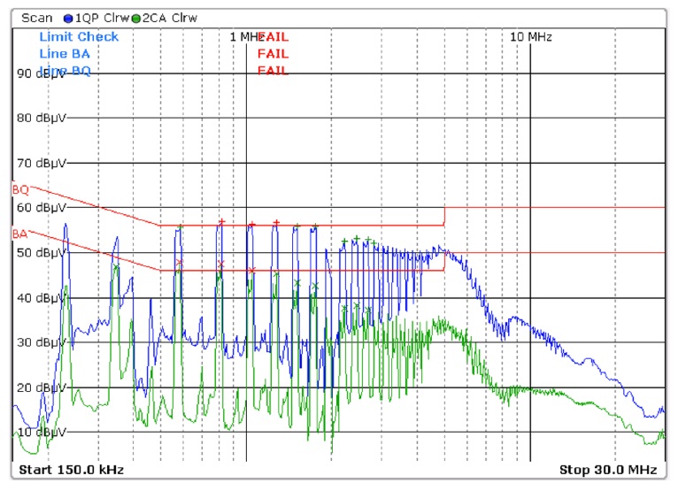
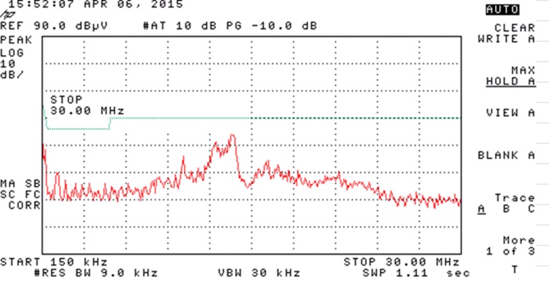
Fig. 1: An OEM’s 250-W external power supply failing emissions at low load conducted emission at 25-W load (10% of rated load).
Blue: Quasi-peak scan. Green: Average scan.
BQ line: CISPR11 class B l Quasi-peak limit. BA line: CISPR11 class B Average limit.
Case Study #3: An OEM’s 30-W Energy (See Fig. 2) Star Level VI external power supply with green-mode variable-frequency fly-back topology.
We tested the power supply at different line and load conditions. We found that it passed conducted emissions with a comfortable margin at 120 Vac full-load but lost all of its margins at 240 Vac and actually failed at reduced load regardless of line voltage. It also failed Average Conducted Emission at a 15-W load (50% of rated load) and 3 W (10% rated load), regardless of line voltage.
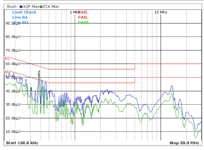
Fig. 2: An OEM 30-W Level VI external power supply.
Blue: Quasi-peak scan. Green: Average scan.
BQ line: CISPR11 class B Quasi-peak limit. BA line: CISPR11 class B Average limit.
Note: Green plot (Ave. scan) exceeds Average limit line.
Conducted emission at 240-Vac 30-W load (100% of rated load).
Examples of system filters negatively impacting EMI performance
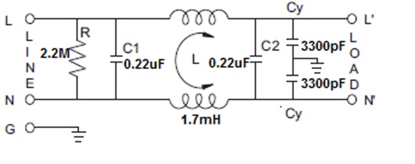
Two different power entry modules were used with the same power supply to demonstrate its impact to the EMI.
The power supply under test with resistor load had the CE margin of at least 6 dB under the Class B limit.
The power entry module from supplier A was first used as the interface between mains and the power supply under test. The conducted emission was tested and found that it failed by 3.5 dB over the limit.
Supplier A filter does not work well with the power supply under test.
The power entry module from supplier A was replaced with a filter from supplier B. The conducted emission was performed again with the same test condition. The result showed that it passed by 5 dB under the limit.
Supplier B worked well with the power supply under test.
Conclusion
In many end applications, peak power occurs for a short period of time, while the constant load power is often at around 50% or less of the rated power of the supply. When in idle mode, the system may enter the low power consumption mode. The system is required to comply with EMI emissions levels through all of these operating conditions. With the end application in mind and lessons from the above case studies, it is essential to perform conducted emissions tests at 100 Vac, 120 Vac, and 240 Vac and load current sweeps from zero to full load, or at least at 100%, 50%, and 10% of rated load to ensure compliance to internal norms.
Power entry modules are designed as a low-pass filter, controlling both the common-mode and differential-mode current. When in the system, it could cause resonance due to its inductive and capacitive reactance interfering with the power supply EMI filter. Choosing an appropriate power entry module with the right capacitance and inductance to use with the power supply is critical.
Advertisement
Learn more about SL Power


