Emulated ripple makes step-down conversion easy
ERM converters simplify switched mode power supplies and make it easy to get a stable system with low output ripple
BY FREDERIK DOSTAL
National Semiconductor
Santa Clara, CA
http://www.national.com
Power management was revolutionized about 20 years ago when easy-to-use integrated switching regulators were introduced. Until then, many applications used linear regulators as voltage supplies or more complicated switch-mode power supplies that required significant expertise. Today, simple dc/dc regulators, such as National Semiconductor’s Simple Switcher family, are used in many different applications.
The regulator power supply’s loop stability is either provided with fixed internal compensation, limiting freedom in selecting the output-stage inductor and capacitor, or the compensation is external, giving the designer flexibility in selecting power-stage components but making the design process more challenging.
Recent improvements use a new control mode, emulated ripple mode (ERM), to simplify power designs. With this mode, engineers don’t need to worry about stability, how to compensate the control loop, or how to achieve low output ripple voltage.
Taming hysteretic-mode converters
Compared to voltage-mode control and current-mode control architectures, hysteretic-mode control needs no compensation components. The hysteretic-mode converter’s control loop is unstable by definition. In such regulators, the output voltage is kept within two hysteretic thresholds.
A new on-cycle in the switch is initiated as soon as the output voltage drops below the low threshold. When the high-level threshold of the hysteretic comparator is reached, a cycle is terminated.
This type of control is very simple to do. No oscillator and no control loop management is necessary, but such a design has one drawback: Some feedback voltage ripple is always needed for correct operation.
If the output voltage were filtered with very low equivalent series resistance (ESR) large-sized capacitors, such as ceramic type components, the output ripple would be very low, but the hysteretic thresholds would not be reached correctly. Such capacitors with very low ESR actually see a voltage ripple that is phase shifted to the actual on- and off-times of the switching node.
In a hysteretic-mode control you need the feedback voltage to increase during the on-time and decrease during the off-time. Only then do you get the right command signal from the hysteretic comparator for the next cycle. Very-low-ESR-output capacitors would reduce the output ripple voltage and remove the ripple voltage needed for the hysteretic comparator. This is where emulated ripple mode (ERM) control comes in.
ERM control
ERM converters sense the inductor current during the off-time and inject some of that ripple as ac voltage onto the error amplifier input voltage. This ac component of the ripple has the correct phase for the on-time and off-time creation for the hysteretic mode control.
The ac part of the hysteretic comparator input is only seen where it is needed, at the hysteretic comparator and not on the actual output voltage of the converter. This feature allows the use of very low ESR ceramic output capacitors in hysteretic mode designs. The National Semiconductor LM3100, LM3102 and LM3103 Simple Switcher regulators offer this feature.
Figure 1 shows how ERM is set up in a step-down regulator circuit. The capacitor between the diode node and the reference voltage of the error amplifier implement ERM.
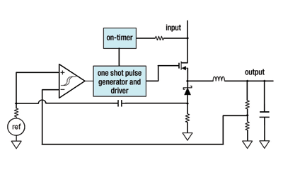
Fig. 1. Step down hysteretic regulator with emulated ripple mode.
How to measure output voltage ripple
When designing a power supply for low output voltage ripple, it is very important to understand what output ripple voltage actually is. When measuring the output voltage of a power supply with a scope probe, actually two ac components can be seen.
The component usually considered “ripple” is the output voltage variation in regards to ESR of the output capacitor or the ripple caused by the capacitance itself. The ESR components of this ripple are usually larger than the capacitance component. With ceramic output capacitors, however, the ESR component is smaller than the capacitance component of the ripple.
Figure 2 shows the output ripple voltage of a buck regulator with an electrolytic output capacitor where the ESR effect is greater than the capacitance effect on the ripple voltage. Figure 3 shows the output ripple voltage on a circuit with only ceramic output capacitors with very low ESR. Here the ripple voltage is mostly defined by the capacitance and not the ESR. The ripple waveform looks more like a sine wave rather than the ESR-caused voltage transitions in Fig. 2. On both plots, channel 1 is the switch-node voltage and channel 2 is the output voltage measured in ac mode.
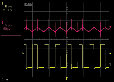
Fig. 2. Output ripple waveform with higher-ESR output capacitor.
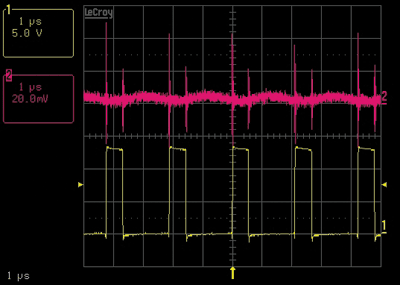
Fig. 3. Output ripple waveform with very low ESR output capacitor.
Figure 4 shows an arbitrary measurement done without paying much attention to the exact measurement setup. Here we see very large voltage spikes during the switching transitions. They exceed the actual ripple amplitude, but are usually not called ripple voltage. The peak-to-peak voltage of these spikes is more than 1 V in this example.
These are noise spikes mostly picked up by the measurement setup. They are very high frequency and come from the transition times of the power FET. The whole power supply board sees large di/dt traces coming from the full output current of the design switching to and from zero current within only a few nanoseconds upon switching transitions.
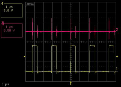
Fig. 4. Output ripple voltage plot with switching noise picked up in measurement.
Figure 5 shows a measurement on the LM3102 evaluation board with a scope probe attached to the output voltage by clipping the tip to the output connection and by clipping the 5-in.-long, high-impedance ground wire to the board’s ground connection. The relatively long ground wire acts like an antenna and picks up di/dt noise of the board.
You can perform the same measurement and reduce the measured output voltage spikes significantly by removing the long ground-connection antenna and using a piece of bus wire, wrapping it around the ground of the scope probe tip and connecting it to a ground that is very close to the output voltage. To keep the ground-loop as small as possible, you measure across the output capacitor on the design directly.
Figure 6 shows a measurement with such a tight scope probe ground connection, eliminating most of the switching noise from the measurement. This measurement technique was used for the waveforms shown in Figs. 2 and 3.
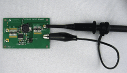
Fig. 5. Arbitrary measurement setup with long probe ground connection.
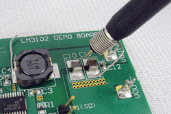
Fig. 6. Very short measurement with ground loop connection.
An easy way to reduce the switching spikes on the output voltage ripple plot is to turn-on bandwidth-limiting on the scope. After making the measurements performed in the paragraph above, it is okay to turn on bandwidth limiting since the signal seen is mostly measurement related and not a real voltage spike on the output voltage. On Figs. 2 through 4, bandwidth limiting on the scope was turned off.
Low output ripple voltage is easy to achieve
Creating low-output-voltage ripple hysteretic-mode regulators with emulated ripple mode is very easy to do. There is no loop compensation to worry about and using ceramic output capacitors for low output ripple voltage works well.
When studying the ac output voltage it is important to distinguish between ripple and noise. Also the measurement technique used is essential for interpreting the result. ■ ■
For more, see the two video files at http://www2.electronicproducts.com.
Advertisement
Learn more about National Semiconductor


