Energy harvesting from an ambient electric field
Energy harvested from an ambient electric field could monitor power lines for the smart grid
BY KARTHIK KADIRVEL
Design Engineer, and
BRIAN LUM-SHUE-CHAN
Design Engineer
Texas Instruments
Energy harvesting from an ambient electric field is a viable solution for applications where solar power is not readily available. Some examples include monitoring power lines to enable the “smart grid,” occupancy sensors in residential and office buildings where the ambient light can be very low, and monitoring rotational machinery. In these applications, a readily available source of time-varying electrical field is available from which energy can be harvested to do useful work. In this article, a power management solution is provided for extracting maximum energy from the electric field to charge and efficiently manage the batteries.
Typically, a wireless sensor node (WSN) is used in these applications. A WSN consists of an energy harvester, rechargeable battery (or supercapacitor) to store harvested energy, electronics to measure the parameters of interest, and a wireless transmitter and receiver.
To maximize a system’s run time in these applications, it is critical to extract the maximum possible energy to charge the battery. Furthermore, by increasing the energy harvested, the time required to charge the battery is decreased. The simplest implementation of an ambient electric field harvester consists of a current transformer (CT) that can operate at mains frequency, a Schottky diode for rectifying the output voltage of the CT, Zener diodes for clamping the voltage output of the rectifier, and an output filter capacitor which are electrically connected as shown in Fig. 1 .
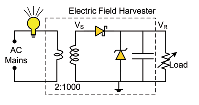
Schematic of circuit used to determine maximum power point of electric field harvester.
When there is current flow in the primary circuit, an electric field proportional to the current is generated. By the principle of induction, a current proportional to the electrical field, scaled by the transformer ratio, is induced in the secondary coil. The large voltage generated at the CT output corresponding to the secondary current is rectified and clamped using Schottky diodes and Zener diodes, respectively. The clamped voltage is filtered by the output capacitor to produce a dc-voltage. The rectified dc-voltage can be used to drive a load. A plot of the waveforms at the input and output of the rectifier is shown in Fig. 2 .
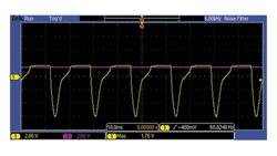
Waveform at the secondary (VS ) of the transformer and the rectified voltage (VR ).
To extract the maximum power from the harvester, the maximum power point (MPP) of the harvester is experimentally determined using the setup shown in Fig. 1. In this example, a light bulb that consumes 65 W is used to energize the primary coil. A resistive load, connected to the output of the harvester, is varied and the power dissipated in the load is plotted as a function of the rectified voltage (see Fig. 3 ).
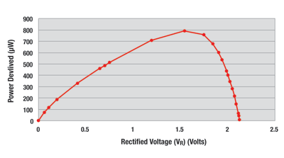
Power delivered to the load as a function of the rectified voltage. Maximum power is obtained at approximately 1.4 V.
It is evident that there exists a voltage at which maximum power can be extracted. For the system under consideration the MPP occurs at 1.6 V. The ratio of the rectified voltage at MPP to the voltage under no load is measured to be 76%. Theoretically, for a sinusoidal current source rectified by a half wave rectifier, maximum power can be extracted from the source when the rectified voltage is regulated to 70.7% of the maximum voltage. In this application, due to the presence of the Zener clamps, the output current waveform is not purely sinusoidal. Hence, the maximum power point is shifted and occurs at 76% of the maximum rectified voltage.
To extract the maximum power from the harvester, the rectified voltage must be regulated to the MPP. Also, the voltage must be boosted up to charge a battery. Figure 4 shows a high-level block diagram of an input regulated boost converter that can regulate the rectified voltage, which is suitable for this application.
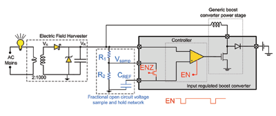
Block diagram of input-regulated charger used to extract maximum energy from an ambient electric field harvester.
Here’s how the circuit operates. The charger periodically turns off when the EN signal goes low. During this time, VR goes to the open circuit voltage. A fraction of this voltage, determined by resistors R1 and R2 , available at the VSAMP node, is sampled by the IC onto a cap (CREF ). The integrated circuit (IC) then regulates VR to the sampled voltage, thus, allowing the harvester to extract maximum power.
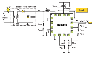
Schematic of system showing energy harvesting from ambient electyric field used to charge a battery band drive a load. Maximum power point tracking is set by resistors ROC1 and ROC2 ..
As an example, Fig. 5 shows a schematic of a solution using the bq25504 IC to extract maximum energy from an electric field harvester and charge a battery. This input regulated boost converter with battery management can be used for charging batteries. The fraction of the open-circuit voltage at which the input should be regulated to extract the maximum power can be programmed using resistors ROC1 and ROC2 . To manage the battery, the IC has programmable thresholds for the over voltage and under voltage settings. This converter also has a battery_ok flag which goes high at a user programmable level. The overvoltage, battery_ok, and undervoltage settings were set to 3.1, 2.8, and 2.2 V, respectively. In this application, the harvester charges a Maxell LR2032 Li-ion battery. The MPP ratio was set to 76%. The load connected to the circuit consisted of a MSP430-based temperature sensor with a 2.4-GHz wireless radio.
In summary, we demonstrated a wireless sensor node powered by the energy harvested from an ambient electric field. An ultra-low-power boost converter like the bq25504 can extract maximum power from an energy harvester and manage a rechargeable battery. To increase the power harvested, a full-wave rectifier or a transformer with a lower turns ratio can be used. ■
Advertisement
Learn more about Texas Instruments


