BY MOHAMMED ZAMAN, Director, Product Applications
& DUANE YOUNKIN, Test Engineering Lead
Qualtré, Inc.
www.qualtre.com
When selecting a MEMS gyroscope, systems engineers and application developers focus on a few key performance parameters. The most common include device sensitivity and bias stability. Sensitivity is important because it refers to the projected output of the device to a certain input rotation. Bias stability, however, has been long considered the “gold standard” specification for gyros and describes the resolution floor of the gyroscope and thereby specifies the detection limitations. The bias of a vibratory gyroscope is the average output recorded from the gyroscope when it is not undergoing any rotation. It is often referred to as the Zero Rate Output (ZRO) and is typically expressed in units of deg/hr or deg/s. Bias stability measurement describes how the bias of the gyroscope may change over a specific period of time under fixed conditions (i.e. constant temperature and pressure).
In most practical applications, however, environmental factors affect these specifications. Most MEMS datasheets specify the impact of temperature on sensitivity and bias. A user can then use this information to calibrate their applications to account for this error. Most datasheets however don’t mention vibration immunity. The impact of the latter often involves complicated solutions such as additional assembly requirements and in some cases integration with additional sensors such as accelerometers for correction. Even this can only correct for certain degree of error [1].
In an ideal world, where a gyroscope should measure only rotation and nothing else, all gyroscopes have some sensitivity to acceleration due to asymmetry of their mechanical designs and/or inaccuracies in the micromachining process. In fact, there are multiple manifestations of acceleration sensitivity, the severities of which vary from design to design. The most significant are usually sensitivity to linear acceleration (or G sensitivity) and vibration rectification (or G2 sensitivity). Since most gyros are used in devices that move about and/or rotate through the Earth’s 1-G field of gravity, sensitivity to acceleration/vibration represents the largest error source.
Random vibration characterization results
Because “real-world” vibrations are not purely sinusoidal in nature, sine-testing procedures have limited practical use. Random vibration testing is a more realistic simulation of actual applications because of simultaneously includes a range of all forcing frequencies. Random vibration testing usually specified using a power spectral density (PSD) plot. The shape of the PSD plot defines the average acceleration of the random signal at any given frequency. The area under this curve is called the signal mean square (G2) and its square root is equal to the acceleration’s overall rms value.
The PSD used to implement a 9-Grms input random vibration signal for MEMS gyroscope performance evaluation in our study is shown below:

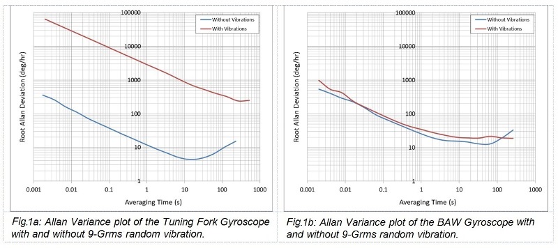
Two different commercial MEMS gyroscopes were characterized in this study – a traditional tuning-fork gyroscope and a bulk-acoustic wave (BAW) gyroscope. The experimental result for the shift in offset due to random vibration stimulus to the yaw-axis is summarized below:

The above characterization data shows a dramatic difference between the two gyroscopes in terms of vibration rejection immunity. An end user however may use a more familiar Allan Variance plot (Fig. 1 ) to draw a similar conclusion.

The challenge many are faced with is most datasheets do not specify parameters associated with random vibration such as linear acceleration and vibration rectification errors. Therefore an inexperienced user may choose to select a gyroscope based on the best reported bias stability value which is typically reported in absence of any random vibration. The impact of susceptibility to random vibration only appears when the user employs the particular gyroscope in his/her application.
Tuning-fork versus BAW technology
To understand why consumer tuning-fork architecture performs poorly against BAW technology it is important to understand the fundamental difference between the two technologies. Although all vibratory MEMS gyroscopes rely on the rotation-induced Coriolis force, the operating modes of the two technologies are different. In a tuning fork device, there is a transfer of energy between two flexural modes of a proof-mass held in place via suspension springs. This design is low-frequency, typically between 10-50 kHz, and is inherently compliant [2]. Commercial tuning-forks which have achieved superior vibration performance have done so using additional proof-masses which have relied on making the mechanical vibration common mode. An example of this is referred to as differential quad-sensor technology, which rejects the influence of linear acceleration and vibration. This solution however comes at the expense of increased die area, package size, and cost.
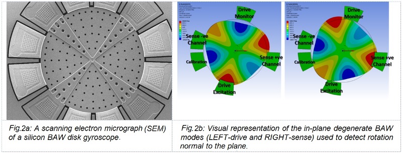
In contrast, BAW technology relies on transfer of energy between two bulk-acoustic wave modes of a circular solid disk or annulus (Fig. 2 ). The operating frequency range of the BAW modes ranges between 2-10 MHz. This is an inherently rigid construction and is far less susceptible to vibrations and size to performance relationship is not compromised.

So when selecting a MEMS gyroscope component, one must select a device that has been designed to minimize the largest error source – in most “real-world” applications; this is most likely vibration sensitivity. Bias stability has often been a key selection criterion for MEMS gyroscopes, but a closer inspection of the vibration performance parameters will be a better predictor of the actual performance one should expect to see in the field, without the need for additional costs that are the result of additional sensors and/or the development of stringent fusion algorithms.
References
[1] Harvey Weinberg, Gyro Mechanical Performance: The Most Important Parameter, Analog Devices Online Technical Article
[2] Yan Michalevsky & Dan Boneh, Gyrophone: Recognizing Speech from Gyroscope Signals, Stanford University Applied Crypo Group Online Article
Advertisement
Learn more about Qualtre


