BY ILA PAL
Chief Operating Officer
Ironwood Electronics
www.ironwoodelectronics.com
Over the past several years, the speed and functionality of IC devices have continually increased. These changes have been accompanied by new package styles featuring higher I/O pin counts with decreased spacing and reduced interconnect feature size. All these factors combine to place more demanding requirements on the IC connector, that is, the socket or adapter used for interconnection.
An IC connector is an electromechanical device that implements a pluggable interface between an IC package and a system circuit board or subassembly. This interface must provide maximum repeatability and minimal effect on signal integrity. A major reason for using a connector is that it can provide for a removable interface and it may also be required for ease of assembly, upgradeability, maintainability, and cost savings. In the field, a socket can enhance maintenance, testing, replacement, or upgrades; the latter may become a critical factor in product life cycle due to technology evolution and IC availability.
In a typical connector (fig. 1 ), each connector pin in an array configuration is a single-piece, integrated-clip design and is made of heat-treated Beryllium Copper Alloy 172 with 30 µin. of gold over 100 µin. of Nickel finish. The socket pin is press-fit into the polyimide substrate directly.
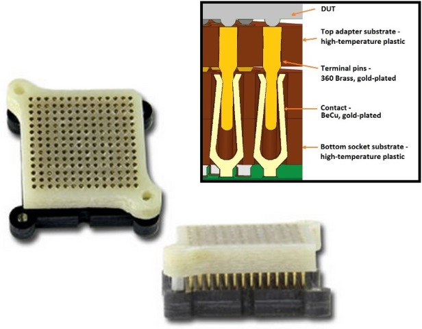
Fig. 1: The 0.5-mm-pitch array connector shown is typically used for interfacing to high-frequency ICs.
At GHz level operating frequencies and beyond, it has become increasingly important to understand the scattering and reflection properties of traveling waves when an interconnection network is inserted within a transmission line between an IC device and the attaching pc board. S-parameter measurements, in terms of reflection coefficients and transmission gain, have typically been made using network and signal analyzers coupled with special test fixtures and probing devices. Based on these measurements, network analysis provides the appropriate S-parameters from which impedance values may be derived and directly correlated via the use of Smith Charts.
Test approach
To examine test requirements, let us consider an oscillator as an example. An oscillator always employs a sensitive amplifier whose output is fed back to the input in-phase. Thus, the signal regenerates and sustains itself. The oscillator selected for a particular application should be capable of supplying an output signal whose upper and lower frequency limits exceed those required by the application. To verify the functionality of an oscillator, it is better to plug it (via connector) into an application board, thereby eliminating solder/de-solder routine and avoid any damages to oscillator. Let’s say a 20-GHz oscillator is selected for the particular application. Then the chosen connector has to accommodate a 20-GHz frequency without significant loss.
The RF performance of the connector can be verified using the following methodology. For so-called G-S-G configurations, a signal (S) pin surrounded by grounded (G) pins is selected for the signal transmission. For G-S-S-G configurations, two adjacent pins are used and all other pins are grounded. Measurements in both frequency and time domain form the basis for the evaluation. Parameters to be determined are pin capacitance and inductance of the signal pin, the mutual parameters, the propagation delay and the attenuation to 40 GHz.
Capacitance and inductance for the equivalent circuits were determined through a combination of measurements in the time and frequency domains. Frequency domain measurements were acquired with a network analyzer (Keysight/Agilent/HP8722C). The instrument was calibrated up to the end of the 0.022-in. diameter coax probes that are part of the test fixture. The device under test (DUT) was then mounted to the fixture and the response measured from one side of the contact array. When the DUT pins terminate in an open circuit, capacitance data can be collected; when they terminate in a short circuit, inductance data can be determined.
Testing was performed on the connector shown in fig. 1 with a test setup that consists of a brass plate that contains the coaxial probes. The DUT was aligned and mounted to that plate. The opposite termination was also a metal plate with coaxial probes (the actual device to be tested or a flat plate with embedded coaxial probes). Measurements were performed for a corner pin of the contact array, a pin at the perimeter (edge), and a pin in the center (field).
Test results
For the frequency range of 50 MHz to 40 GHz, insertion loss was measured (fig. 2) at less than 1 dB to about 13.5, 19.7 and 20.1 GHz (corner, edge, and field pins, respectively). The 3 dB point is not reached before 35.1 GHz for the corner pin and >40 GHz for edge and field pins.

Fig. 2: Using the test methodology presented here, the above S-parameter data was obtained for corner, edge, and field array pins.
An insertion loss of 1dB at 20 GHz means that 90% of the signal is passing through the interconnect medium at 20 GHz with only 10% signal loss. Note that, while both field and edge pins show a 1dB loss at 20 GHz, the corner pins show 1dB loss at 13.5GHz and about 1.6 dB loss at 20 GHz. Thus, in addition to contact geometry, location of the contact pin plays a significant role in RF performance. This is very critical for the test engineer, since the specific pin functionality of the DUT must be verified at a specific frequency.
Of primary concern to anyone using high-frequency devices is that the connector must provide high electrical performance while meeting other mechanical requirements. The electrical path of the connector is a high-priority performance issue; the physical length from the top connection point to the solder tail on the bottom of the connector, along with the physical geometry, determines the connector’s ability to perform at a specified frequency. This is the shortest connection length by far for interconnect pin sockets, therefore providing better transmission of high frequency signals.
Advertisement
Learn more about Ironwood Electronics


