By Chinmay Honrao and Nazzareno (Reno) Rossetti, Maxim Integrated
Industry 4.0 has given us smart factories, which are highly digitalized and connected for adaptive manufacturing on one end and increased throughput on the other. This has not only led to improved productivity, but has also made it possible to identify and fix any breakdowns on the factory floor in real time without need for much human intervention.
For the past several decades, automation has been the key driving force in increasing factory efficiency. With advances in communication, big data, artificial intelligence (AI), and the internet of things (IoT), we are moving ever closer to making factories truly smart.
According to a report [1] published by Capgemini Research Institute and Digital Manufacturing services, smart digitalized factories could add $500 billion to $1.5 trillion to the global economy in the next five years. This report also predicts that the next few years will see a 7× annual growth in overall factory efficiency.
One of the important pillars on which these smart digital factories are being built is connectivity. The connected factory uses an IoT framework to connect devices, assets, and sensors across the factory floor. These sensors and devices gather data not only from tools and machines, but also from materials, goods, indoor vehicles, and even personnel on the factory floor. The data gathered from these connected devices can be analyzed, using AI to identify trends, patterns, and key insights into the daily operations and workings on the factory floor, ultimately resulting in reduced machine downtime and added flexibility for the factory.
To seamlessly enable this, wireless beacons are attached to equipment and materials, making them trackable either with simple apps based on smartphones or with more sophisticated, server-based systems. These beacons need to be small, cost-effective and long-lasting, while being powered by inexpensive disposable batteries. Wireless technologies used in these applications could include Wi-Fi, Bluetooth Low Energy (BLE), ultra-wideband (UWB) and radio-frequency identification (RFID), each with varying degrees of location accuracy, range, and battery life. Note that these standards are sometimes referred by their IEEE number such as 802.11 and 802.15.x.
The beacon’s transmit power (which also depends on the range over which the data needs to be transmitted) and the frequency of transmitting events play an important role on battery life. Finally, the beacon’s electronics must minimize its impact on power consumption.
BLE beacons are typically favored in many applications as they provide high positional accuracy, while still being inexpensive and consuming little power.
In this design solution, we review the challenges of powering a BLE beacon and show how an efficient on-board voltage regulator can improve its battery life.
![]()
Fig. 1: Bluetooth beacons in the smart factory.
Typical beacon system
Fig. 2 shows a typical beacon block diagram. A single alkaline battery, supplying a charge of up to 2,700 mAh powers the on-board controller, sensors, and radio through a DC-DC step-up regulator. It is not uncommon to see a single coin-cell in some systems although we used AA battery in this design solution.
![]()
Fig. 2: Typical beacon block diagram.
The various sensors collect data, which is then transmitted by the radio for 20 ms to a centralized receiver; for the next 980 ms, the beacon is in sleep mode.
In sleep mode, the boost converter is loaded with a leakage current of 0.73 µA, while a radio current pulse of 3.182 mA peak is required for data transmission. The boost converter load profile is shown below in Fig. 3 .
![]()
Fig. 3: Beacon current profile.
In one typical indoor asset tracking application, the system must last for two years using only a single alkaline battery. A typical boost voltage regulator has a leakage current of 0.2 µA, quiescent current of 10 µA, 85% peak efficiency, and 50% efficiency at low current. Assuming 1.5-V input and 3.3-V output voltage, with an output sleep current of 0.73 µA, we can calculate the average current as follows:
![]()
This average current of 168 µA will cause the battery to fall 61 days short of two years.
The challenges
Achieving high efficiency with a small size is challenging for any voltage regulator. Increasing the frequency of operation of the voltage regulator will reduce the size of passives but will result in increased losses, thereby reducing its efficiency. Having the input operation range of the regulator down to fractions of a volt is critical, as the battery voltage falls continuously during operation. The proliferation of indoor tracking applications creates a need for multiple customized versions of voltage regulators, especially with respect to input/output voltage and current specifications. Accordingly, a beacon manufacturer may be forced to maintain a sizeable and costly inventory of different regulators and the passives required to support them.
The solution
The ideal solution is a load-aware voltage regulator that addresses these shortcomings, namely one that continuously monitors the system’s current consumption behavior. The MAX17222 nanoPower synchronous boost converter is such a device. It offers high efficiency, a 400-mV to 5.5-V input range, a 0.5 A peak inductor current limit, and an output voltage that is selectable using a single standard 1% resistor. A novel True Shutdown mode yields leakage currents in the nanoampere range, making this a truly nanoPower device.
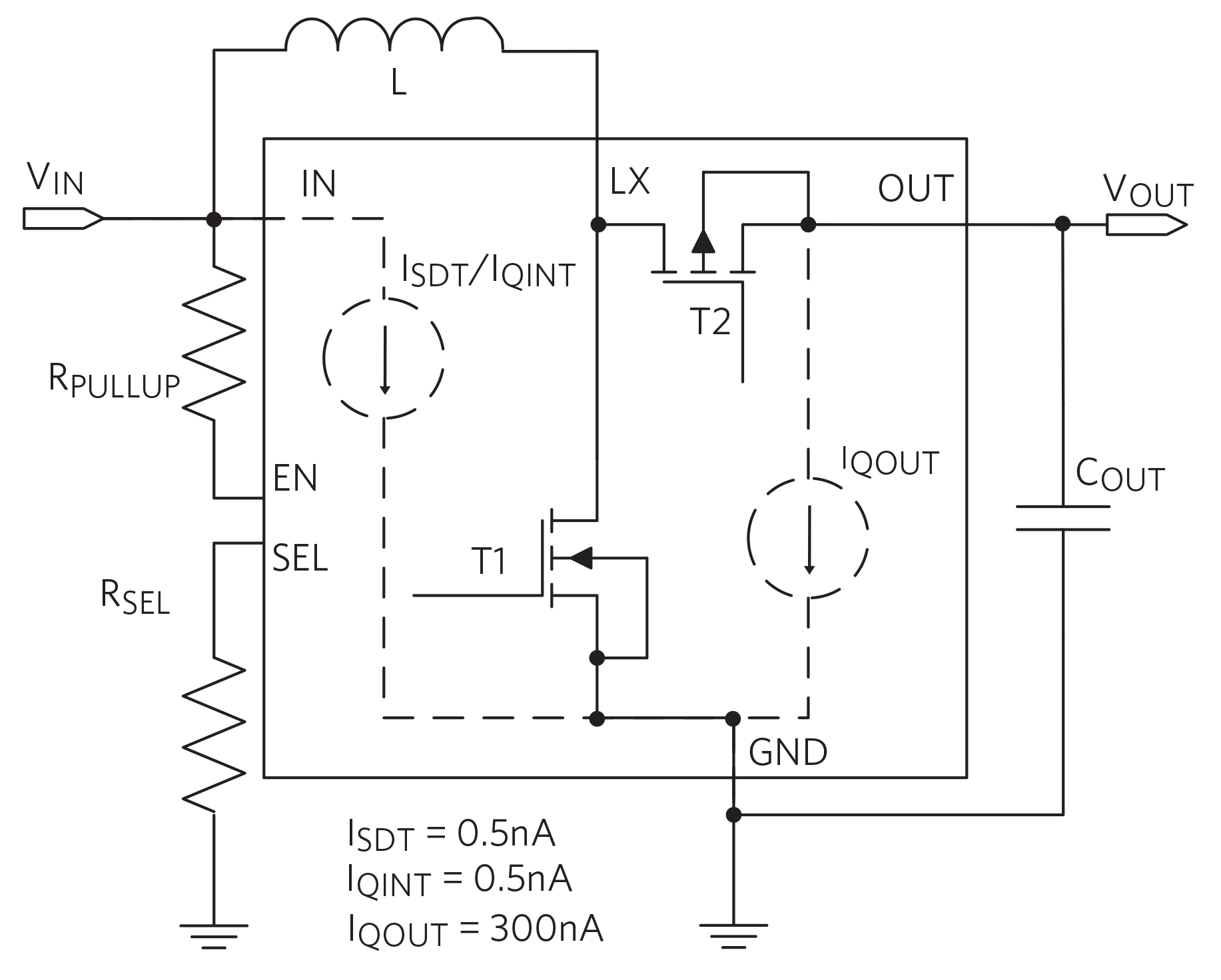
Fig. 4 illustrates the basic elements of the IC with respect to shutdown and quiescent currents.
‘True Shutdown’ current advantage

Fig. 4: Shutdown and quiescent currents.
The True Shutdown feature disconnects the output from the input with no forward or reverse current, resulting in very low leakage current. If a pullup resistor is used to enable/disable operation, the pullup current in True Shutdown mode must also be accounted for. If instead, the enable (EN) pin is driven by a push-pull external driver, which is powered by a different supply, then there is no pullup current and the shutdown current is only 0.5 nA, much lower than the 0.2 µA of the typical case discussed earlier.
Quiescent current advantage
Referring to Fig. 4 , the input quiescent current (IQINT ) for the IC is 0.5 nA (enable open after startup) and the output quiescent current (IQOUT ) is 300 nA. To calculate the total input quiescent current, the additional input current needed to feed the output current (IQOUT_IN ) must be added to IQINT . Since the output power is related to the input power by the efficiency (POUT = PIN x η), it follows that:
IQOUT_IN = IQOUT x (VOUT /VIN )/η
If VIN = 1.5V, VOUT = 3.3 V, and efficiency η = 57.5% at low current, we have:
IQOUT_IN = 300 nA x (3.3/1.5)/0.575 = 1148 nA
Adding the 1148 nA to the input current of 0.5 nA yields a grand total input quiescent current of 1148.5 nA (IQINGT ). This quiescent current is nine times lower than the 10 µA of a typical step-up voltage regulator, as discussed in the previous case.
Efficiency advantage
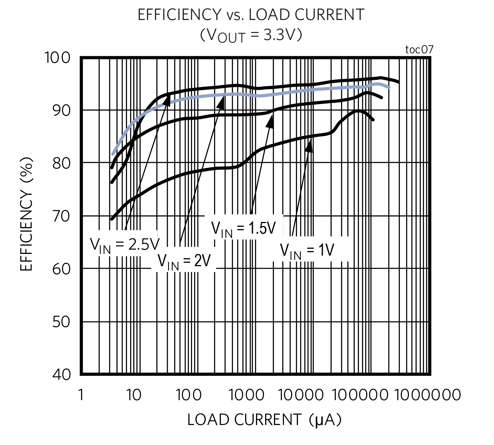
The boost converter IC features low-RDSON, on-board powertrain MOSFET transistors that yield excellent efficiency even when operating at frequencies high enough to warrant a small overall PCB size (Fig. 5 ).

Fig. 5: High efficiency.
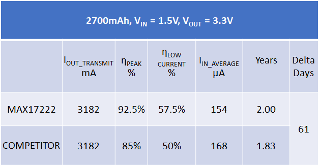
With the boost converter’s 92.5% efficiency at peak current, 1.15 µA quiescent current, and 0.5 nA shutdown current, the beacon can last more than two months longer than with a typical voltage regulator (See Table 1 ).
Table 1. Battery Life Comparison Between Two Regulators

Enable transient protection mode
The IC includes an option for enable transient protection (ETP) mode. When activated by the presence of a pullup resistor, extra on-chip circuitry powered by the output capacitor assures that EN stays high during short transient disturbances at the input. In this case, the quiescent current calculated above increases by a few tens of nanoamps.
BOM advantage and smart VOUT selection
The MAX17222 trades off the traditional resistor-divider that is used to set the output voltage value with a single output selection resistor (RSEL ), as shown in Fig. 4 . The chip uses a proprietary scheme to read the RSEL value that consumes up to 200 µA at startup only. A single standard 1% resistor sets one of the 33 different output voltages, separated by 100 mV increments between 1.8 V and 5 V. The result is a small reduction in the bill of materials (BOM) (one less resistor), simplified inventory (a single regulator for multiple applications), and lower quiescent current.
Conclusion
The smart factory concept, driven by digitalization and connectivity, is being embraced by more and more manufacturers around the world to stay competitive in today’s dynamic markets. A key feature of these smart factories is locating and monitoring assets across the factory floor. The collected data can be instantly analyzed and acted upon in real time without requiring constant supervision by operators.
Factory indoor localization and indoor navigation requires wireless beacons that are small, cost-effective, and long-lasting while powered by cheap disposable batteries. In this design solution, we reviewed the challenges of powering a BLE beacon and introduced a boost converter that, thanks to a triple punch of high efficiency, low shutdown current, and low quiescent current, sustains its operation for two years on a single disposable AA battery.
About the authors:
Chinmay Honrao is a business manager in the Core Power Management business unit at Maxim Integrated. Chinmay holds Master’s and Bachelor’s degrees in Material Science and Engineering from the Georgia Institute of Technology and the Indian Institute of Technology Kharagpur, respectively.
Nazzareno (Reno) Rossetti is an analog and power management expert at Maxim Integrated. He is a published author and holds several patents in this field. Reno holds a doctorate in Electrical Engineering from Politecnico di Torino, Italy.
Advertisement
Learn more about Electronic Products MagazineMaxim Integrated


