Integrated bench instruments:
Feature rich yet easy to use
A revolution in instrument design makes operation
more intuitive and less rules oriented
BY CHRIS KELLY
Agilent Technologies
Loveland, CO
http://www.agilent.com
Test bench instrumentation has benefited from miniaturization in semiconductor and printed-circuit technologies, as functions previously found in separate products have been combined into single instruments. While a possible result of the merger of multiple instruments could be complex difficult-to-use products with many different functions overloading the user interface, innovative front-panel design has endowed benchtop instruments with the ability to present even complex functions in simple and usable ways. An example of a single test and measurement instrument that has taken advantage of this bundled functionality is the function generator, which now often includes arbitrary waveform and pulse-generator capabilities. One of the key benefits obtained with this three-instruments-in-one model is a major cost reduction when test benches are initially outfitted. Cost reduction Several factors inside and outside the instrument account for a substantial cost reduction over using single-function instruments. Within the test instrument, overhead costs such as power supplies, cooling fans, chassis, communications, and front-panel interfaces are shared. Components common to three instruments are reduced to one set based on combined functionality, with an associated component cost savings. If the functions are closely related (function generators, pulse generators, and arbitrary waveform generators are all signal sources), then the hardware cost of adding a related function is relatively small–perhaps only 25% of the total cost of the instrumentation hardware.

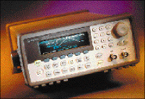
Agilent's 33250A function-arbitrary-pulse waveform generator exemplifies an industry trend toward combining features from individual instruments into a multifunction instrument that is cost effective and easy to use.
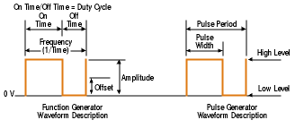
This reduced cost makes it economically viable to add a seldom-used function such as pulse generation to a more common instrument. Sharing certain instruments is a common model in most research and development labs and tech bench areas. When each bench can have permanent use of a multifunction instrument, the time and costs associated with locating, negotiating access, and reprogramming multiple single-function boxes are markedly reduced. Beyond the cost of the instrument itself and the labor savings in finding and setting it up, an integrated instrument saves the user both space and power when laying out a design or test facility. In an automated test system, integrating several related functions into a single instrument saves both rack space and the cost of wiring and switching. Today, it is possible for a half-rack-width instrument to replace two or three older half- or full-rack instruments. In some installations, a reduction in the size and cost of the signal switching hardware could be reduced by perhaps 10% or more (depending on the switch's complexity) through the application of combined instrument functions. In large test systems, decreasing one dimension in a switching matrix can result in savings of thousands of dollars. Additionally, considerations involving the hard-to-measure cost of learning to operate separate instruments should not be overlooked. There is always a “relearning curve” when turning on a rarely used instrument and trying to remember how to make it perform the desired function. Usability testing that targets these problems has made bench instruments increasingly intuitive, enabling engineers to learn, use, and recall complex setups and measurement sequences easily. Usability The task of combining multiple instrument functions into a single product entails much more than simply adding the hardware required to perform the additional functions. In some cases, the instruments being replaced have different use models and without careful design and usability testing, the combination instrument may be confusing and difficult to understand. When function generators and arbitrary waveform generators (AWGs) were initially merged, the model adopted in many of the resulting instruments was that of a direct digital synthesis (DDS) waveform generator. This presented a challenge to AWG users, since generating the waveform clock in DDSs differs from that in traditional AWGs. The advantages of DDS, such as very-high-resolution frequency control, outweighed the difficulties in most cases. Today, most function generators simply treat arbitrary waveform generation as another function similar to sine and triangle wave generation, with the exception that the user supplies the waveform. Adding features A more difficult step in our function generator (now a function/arbitrary waveform generator) is adding a true pulse-generation capability to our integrated instrument. While a square wave from a function generator may appear similar to a pulse-generator output, the two instruments are conceptually different in many ways. The functionality of these instruments is different, and the challenge for instrument manufacturers is to combine different use models in a way that allows both to be used without resulting in a sea of confusion. Function generators present signal amplitude as amplitude plus offset, which means that the peak-to-peak (or rms) voltage of the waveform is specified, and a dc-offset voltage is added to the waveform. In this case, a 2-Vp-p square wave signal varies from –1 to +1 V, and a dc-offset voltage may be added to move the waveform up and down as seen on an oscilloscope. This same function in pulse generators is usually specified quite differently. Pulse generators are often used for digital circuit stimulus where signal amplitude is specified as a high-level voltage or low-level voltage, so a pulse may have a high-level (on) voltage of 2.5 V, and a low-level (off) voltage of 0 V. If the instrument only allowed the setting of signal amplitude using the function-generator model, a number of calculations would be required to set up the amplitude correctly. Beyond these initial setup considerations in our two-instrument-use models, consider the additional complexity of trying to vary only the high-level voltage. Establishing the switching-voltage threshold of a digital circuit in the pulse-generator model, the user selects the high-level parameter, and adjusts the knob to obtain the desired result. If the function generator allows only amplitude and offset, the task would require simultaneous adjustment of both amplitude and offset to achieve the high-level setting while keeping the low level at 0 V. Example expanded In a more complex example, suppose the user must evaluate the effect of varying the repetition rate of a 1-ms pulse on a circuit. In a function-generator model, the user may select a square wave of a certain frequency and duty cycle to obtain one operating condition. The setup is frequency-domain units, and the problem is a time-domain issue. The pulse-generator user (accustomed to dealing with time-domain instruments) will specify pulse repetition rate and pulse width in time units. To pound the idea home, consider what the user must do to vary the repetition rate of a 1-ms pulse. In the function-generator model, two parameters–waveform frequency and waveform duty cycle–must be simultaneously adjusted to keep the pulse-width constant while varying the repetition rate. It is virtually impossible to make this waveform change reliably with a function generator. However, with a pulse generator, the user simply adjusts the pulse repetition rate of the constant-width pulse (see Fig. 1 ).

Fig. 1. A function generator describes a pulse using totally different parameters.
The different use models of the function generator and the pulse generator make the merging of the two instruments difficult. But the benefits of accomplishing such a task make the challenge worthwhile. This is where usability modeling and testing have made real contributions, and new instruments show the results. Usability testing solutions Usability testing has clearly shown that users want to focus squarely on the problem they are solving and not get bogged down in setting up the instruments needed to do the work. By presenting setup in units and methods that are familiar, instrument operation is less distracting, and the focus is kept on the real task at hand. It is entirely possible to calculate necessary amplitude and offset required to set a function generator to a desired pulse-generator level or to adjust waveform and duty cycle to arrive at a specific pulse rate. However, since the instrument has a processor (or two, or three) inside, it makes much more sense to let the instrument do the conversions. Apart from computational applications, several tools can be applied to the problem of combining different use models in a bench instrument. Primary among these is using a color graphical-display device as the instrument's key user interface. Color presentation Color is a powerful tool for presenting quantities of information in understandable formats. Several unrelated state settings can be simultaneously presented–separated by their various colors and locations on the screen. These may include output states, instrument trigger setups, modulation type, and waveform pattern, which are presented as advisories in smaller zones on the display. Current-waveform frequency (period) and amplitude are major dynamic parameters and are given a prominent location and area for display. Icons are used where ever possible to provide compact feature recognition that is understood without verbal description. The graphical display could also support the use of soft keys on a keyboard adjacent to the display. It is an important feature that only the parameters that apply to the current setup are present on the display, to avoid a panel full of knobs–some of which don't apply to the operation at hand. To take full advantage of the graphical display, output signals can also be viewed and adjusted using a graphical format. In this case, a single key press places the instrument into a mode in which the user sees not only the waveform's numerical parameters, but the shape of the waveform being generated, together with key parameters such as voltage and time values. When a bench instrument of increasing complexity takes an approach to user interface that allows the user to concentrate on the problem at hand rather than on the quirks of the measuring instrument, it can result in a product that becomes second nature to operate.
Advertisement


