Fiber optics breaks rules of conventional sensing
Using light/optical fiber instead of electricity/copper wire makes impossible strain/temperature measurements possible
BY NATHAN YANG
National Instruments, Austin, TX
www.ni.com
Conventional sensors convert physical phenomena (such as temperature, load, pressure, and strain) into electricity, which is then conditioned, sampled, and scaled to the required physical values. Despite their ubiquity, these sensors have inherent limitations such as transmission loss and susceptibility to electromagnetic interference (noise) that make their usage challenging or impractical in many applications. Fiber-optic sensing is an excellent solution to these challenges, using light rather than electricity and standard optical fiber in place of copper wire to perform sensor measurements.
Tremendous innovation in the optoelectronics and fiber-optic communication industries over the past two decades has significantly improved optical component quality while reducing prices. By leveraging economies of scale, fiber-optic sensors and instruments have moved from limited laboratory applications to broad applicability in applications such as structural and other types of monitoring in the fields such as power and energy, transportation, and civil engineering.
A fiber-optic-sensor primer
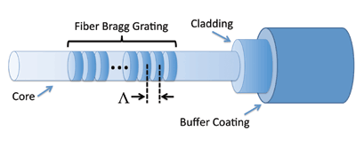
Fundamentally, a fiber-optic sensor works by modulating one or more properties of a propagating light wave, including intensity, phase, polarization, and frequency, in response to the environmental parameter being measured. At the core of optical sensing technology is the optical fiber a strand of glass thinner than the human hair that transmits light within its core. An optical fiber is composed of three main components: the core, the cladding, and the buffer coating (Fig. 1 ). The cladding reflects stray light back into the core, ensuring the transmission of light through the core with minimal loss. This is achieved with a higher refractive index in the core relative to the cladding, causing a total internal reflection of light. The outer buffer coating serves to protect the fiber from external conditions and physical damage. It can incorporate many layers depending on the amount of ruggedness and protection required.
A few optical sensing technologies are available, each providing different features and measurement characteristics. One of the most commonly used and broadly deployed optical sensors is the fiber Bragg grating (FBG), which reflects a wavelength of light that shifts in response to variations in temperature and strain.
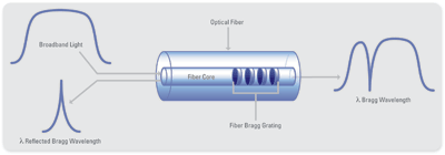
A Bragg grating is a periodic variation of the refractive index within the core of the fiber. When a broad-spectrum light beam is sent to an FBG, reflections from each segment of alternating refractive index interfere constructively only for a specific wavelength of light, called the Bragg wavelength. This effectively causes the FBG to reflect a specific frequency of light while transmitting all others.


Fig. 1. An expanded view of an FBG sensor is shown at left while its operation is shown at right.
Because the Bragg wavelength is a function of the spacing between the gratings, FBGs can be manufactured with various Bragg wavelengths, enabling different FBGs to reflect unique wavelengths of light. Changes in strain and temperature affect both the effective refractive index and grating period of an FBG, which results in a shift in the reflected wavelength.
Because an FBG responds to strain and temperature, both effects need to be distinguished. For sensing temperature, the FBG must remain unstrained. FBG temperature sensors, such as the one pictured in Fig. 2 , are packaged in a way to ensure that no bending, tension, compression, or torsion forces are applied to the FBG. The thermal expansion of glass is practically negligible; thus, changes in the reflected wavelength due to temperature are primarily due to the change in the refractive index of the fiber.

Fig. 2. An example of a temperature optical sensor is the Micron Optics device seen above.
FBG strain sensors are somewhat more complex because both temperature and strain influence the sensor’s reflected wavelength. For proper strain measurements, the temperature effects on the FBG must be compensated for. This can be achieved by installing an FBG temperature sensor in close thermal contact with the FBG strain sensor. A simple subtraction of the FBG temperature sensor wavelength shift from the FBG strain sensor wavelength shift yields a temperature compensated strain value.
Interrogation methods
The ability to create FBGs with unique Bragg wavelengths lends itself well to wavelength division multiplexing (WDM) techniques. This provides the ability to daisy-chain multiple sensors with different Bragg wavelengths along a single fiber over long distances. WDM provides each FBG sensor its unique wavelength range within the light spectrum. Because of the wavelength nature of FBG, sensor measurements remain accurate even with light intensity losses/attenuations due to bending or transmission.
The number of sensors that can be incorporated in a single fiber depends on the wavelength range of operation of each sensor and the total available wavelength range of the interrogator. Because wavelength shifts due to strain are typically more pronounced than temperature, FBG strain sensors are often given a range of ~4 nm, while FBG temperature sensors require ~1 nm. Because typical interrogators provide a measurement range of 20 to 80 nm, each fiber array of sensors can usually incorporate anywhere from one to more than 80 sensors so long as the reflected wavelengths do not overlap in the optical spectrum (see Fig. 3 ).

Fig. 3. Each FBG optical sensor in an array must occupy a unique spectral range.
With typical FBG sensor wavelengths operating within a few nanometers, optical interrogators must be capable of performing measurements with a resolution of a few picometers or less a very small value to quantify. One can choose from several methods for interrogating FBG optical sensors. Interferometers are often used in laboratory settings and can provide high-resolution optical spectrum measurements. However, these devices are usually expensive, large, and delicate. In addition, laboratory optical interferometers deliver either accuracy or speed but never both, which is necessary for optical sensing applications.
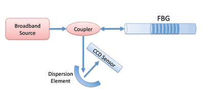
A more rugged method involves the use of a CCD and a fixed dispersive element, sometimes referred to as wavelength-position conversion. With this method, a broadband source illuminates the FBG (or multiple FBGs in an array). The reflected light wave is passed through a dispersive element that distributes the various wavelength components of the reflection to different locations on a linear CCD sensor.


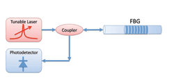
Fig. 4. The wavelength position conversion method of interrogating FBG optical sensors is seen on top, while the tunable-laser approach is seen on the bottom.
This method can yield fast, simultaneous measurements of all FBGs in the array, but offers limited resolution and signal-to-noise ratio (SNR). For example, detecting an FBG peak shift of 1 pm over an 80-nm range requires a linear CCD with at least 20,000 pixels more than four times the pixel count of linear CCDs currently available on the market (as of July 2010). Additionally, the power of a broadband source is spread across a wide wavelength range, producing low-energy FBG reflections that can be difficult to detect.
The most current and popular approach uses a Fabry-Perot tunable filter to create a fast, high-power sweeping laser to replace the traditionally weak broadband light source. A tunable laser concentrates energy in a narrow band, providing a high-powered light source with an excellent SNR. The high optical power generated by this architecture enables a single light source to be coupled with multiple fiber array channels, reducing cost, complexity, and size for multichannel interrogators.
Interrogators based on this tunable laser architecture operate by sweeping a very narrow band of light across a wavelength range while synchronously using a photodetector to measure the reflections from the FBG(s). When the wavelength of the tunable laser matches the Bragg wavelength of the FBG, the photodetector sees a corresponding response. This method can deliver an accuracy of ~1 pm, which translates to typical FBG sensor accuracies of ~1.4 microstrain and ~0.1ºC (sensor dependent). The tunable laser approach also enables measurement over fiber lengths of more than 10 km because of its high optical power relative to broadband alternatives.
Form factor
In addition to the interrogation method, the form factor of the optical sensor interrogator is also important. Traditional optical measurement devices provide fixed software functionality and a fixed user interface. This lack of flexibility limits the system’s ability to meet many structural test and monitoring application needs. Most modern applications require more than a simple interrogator; they might require a controller, in-system data storage, the ability to synchronize with other measurements and log environmental conditions, or even present live data on the web. Selecting an interrogator based on an open, modular platform like PXI helps meet these requirements.
Optical sensor installation
Because the installation and usage of optical sensors are similar to those of conventional electrical sensors, transitioning to an optical sensing solution is reasonably simple. For example, FBG strain gages are available with a variety of form factors and mounting options including epoxy, welding, bolt-on, and embedded. Also, since fiber is widely used in the telecommunications industry, it is subject to strict regulations, which makes it a robust system component. There are, however, two important considerations when making the transition between electrical and optical sensors.
First, optical connectors are susceptible to contamination from dust particles, human hand oils, condensed vapor (air) film residue, powders from water (or other solvents) evaporation and more. One must regularly clean fiber-optic components when they are mated and demated.
A second consideration is related to the bend radius of the optical fiber. Fiber-optic sensing applications often require bending optical fiber over both short and long distances which can increase signal attenuation. As such, fiber-optic cable manufacturers specify allowable bend radii for both short- and long-term bending, for different fiber lengths. ■
Advertisement
Learn more about National Instruments


