Flash driver ICs redefine xenon vs. LED lighting
Flash must offer higher light output without endangering the battery or exceeding the power budget or footprint
BY TOM DELURIO
Advanced Analogic Technologies
Sunnyvale, CA
http://www.analogictech.com
Today’s popular smart phones keep raising the bar for features and functionality. A growing number of handsets now offer embedded cameras that deliver 5-Mpixel resolution or greater in an attempt to match the performance of standalone digital still cameras (DSCs).
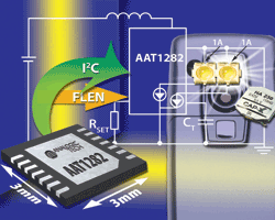
One of the more difficult challenges handset designers have faced is how to deliver the high-intensity flash needed to produce high-resolution still photos in low-light conditions from a single lithium-ion battery (see Fig. 1 ). As camera performance capabilities improve, some handset designers have migrated from flash subsystems that use low-current white-light-emitting diodes (WLEDs) to those using xenon flash lamps.

Fig. 1. High-intensity flash provides lighting needed for high-resolution cameras in cell phones.
Widely used in DSCs, xenon modules offer light output hundreds of times greater than early low-current WLED-based flash subsystems. That, in turn, enables faster shutter speeds and shorter exposure time, and helps minimize the impact of camera motion and prevent blur. As a result, xenon flash systems promise clearer, crisper photos at longer distances and without sophisticated brightness modification, contrast correction, or image stabilization schemes.
From the handset designer’s standpoint, however, xenon flash systems bring a number of crucial liabilities. First and foremost is size. While manufacturers have continually reduced module size, a xenon photoflash is typically driven at high voltage (200 to 300 V) from a low-voltage source using a flyback converter that stores the energy in a high-voltage electrolytic capacitor. Typically these capacitors are approximately 7 mm in diameter, which presents a major problem for manufacturers developing slim, compact handsets.
Moreover, while the xenon flash bulb delivers large amounts of light over a very short pulse, it is primarily designed for the single-shot, high-intensity lighting required for still photography. It does not support the lower-intensity movie-mode lighting required for the video functions now found in most high-performance handsets.
High-current LEDs
In recent years, handset designers have also explored the use of flash-lighting subsystems based on higher-current WLEDs. As current-driven devices, the light output of a WLED depends on the forward current passing through it.
Maximum light output is primarily limited by the maximum average forward current the LED can handle, which is driven by the power dissipation capability of the LED chip package and the performance of the heat sink to which it is attached. Since LEDs operate from a pulsed current with very short duty cycles, their light output can be significantly increased while keeping average current level and power dissipation low. Accordingly, LED photo flashes offer handset designers a highly attractive solution that requires less power consumption than a comparable xenon-based flash with drive circuitry that takes up little space.
To match the photo quality of high-resolution DSCs, however, handset designers must drive flash LEDs at peak currents as high as 2 A. That means the system must deliver up to 400% more power than the handset’s battery can provide to meet required light-intensity levels. That is difficult to do without damaging the handset’s lithium-ion battery.
Some designers have attempted to circumvent this power limitation problem by using longer flash exposure times at lower power levels. But typically these strategies result in a blurry photographic image.
Recent advances in flash driver IC design promise to finally solve this problem. Power semiconductor manufacturers have recently developed new high-efficiency, high-current step-up converters optimized to work with a supercapacitor.
These new devices features two output-current sinks, each capable of providing a regulated 1-A current. Since the two LED current sources share the output current equally, they can be connected to apply full 2-A output current into a single WLED.
Flash LEDs for high-resolution cameras typically require from 1 to 2 A for up to 120 ms. If designers simply used a flash driver IC to drive the LED, the battery would need to supply so much current over the duration of the flash pulse that it would either cause the battery protection circuit to shut down or initiate a low-voltage shutdown with plenty of energy remaining in the battery. By using a boost converter and capacitor, designers can store the current and deliver it quickly without draining the battery.
Conventional capacitors cannot be used in a space-constrained handset design, however. They would require either a very large case or multiple devices connected in parallel. Instead, designers have addressed space limitations by using a very-high-value supercapacitor. Offering high levels of capacitance in a relatively small, flat case, a supercapacitor allows designers to deliver the high current needed for short flash events without compromising the handset’s slim footprint.
Managing in-rush current
While a supercapacitor’s low internal resistance or equivalent series resistance allows it to deliver high peak currents with minimal droop in output voltage, it presents another major problem for handset designers. Since the supercapacitor is initially discharged, once the supply voltage is applied it operates like a low-value resistor. This can result in an excessively large in-rush current if the current is not controlled.
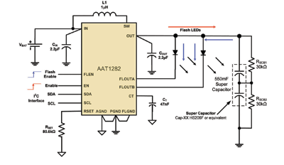
The schematic in Fig. 2 illustrates a typical implementation of a high-current WLED flash subsystem. Here designers have combined a 0.55-F, 85-mΩ supercapacitor from CAP-XX capable of delivering 9-W LED power bursts with the AAT1282 flash LED driver. The boost converter can drive the flash LEDs at current levels between 1 and 2 A. Forward voltage across the LEDs can range up to 4.8 V. To help meet the stringent space limitations of handset designs, this entire flash subsystem is only 2 mm thick.

Fig. 2. This AAT1282 flash LED driver schematic shows a typical implementation for WLED flash.
This new breed of flash driver IC is specially optimized to manage this problem. These devices integrate a fixed-input current limiter that prevents excessive inrush current during startup.
To prevent damage to the flash driver and the supercapacitor from an open circuit, the converter’s output voltage is also limited using internal overvoltage protection circuitry. The converter uses an industry-standard I2 C serial digital interface to enable and disable the LEDs. And unlike xenon tube-based lighting subsystems, this high-current WLED-based approach allows the designer to control LED current across 16 discrete levels using the I2 C interface for movie-mode lighting applications. ■
For more on flash driver ICs, visit http://www2.electronicproducts.com/AnalogMixICs.aspx.
Advertisement
Learn more about Advanced Analogic Technologies


