Flexible designs with I2C programmable battery chargers
Programmable chargers provide a flexible and efficient way of meeting complex system-level requirements and shorten development time
BY MIGUEL AGUIRRE, Systems Engineering Manager, Battery Charge Management
Texas Instruments, Dallas TX
www.ti.com
There are many options available in the market for designing the battery-charging system architecture for portable products. Examples include power-path versus non-power-path topology, linear versus switching chargers, and single input versus multiple inputs. One of the most important design decisions is charger programmability configuration. Among the most popular options for single-cell portable products are standalone and host programmable chargers, with the most popular option in the latter category being I2 C programmability. This article compares these two configuration options and addresses some of the benefits of using an I2 C programmable charger.
Standalone battery charger configuration
A standalone charger configuration is characterized by using passive components, such as resistors and capacitors, to program important charge parameters like charging current, charge voltage, and safety timer. Other system level parameters, such as input current limit, can also be programmed using this configuration with GPIOs.
The benefit of this standalone configuration is simplicity. Only by using external passive components, the full charger subsystem can be designed without the need of developing any software. Figure 1 shows an example of a standalone charging subsystem.

Fig. 1: A standalone battery charger circuit, such as the BQ24075.
Battery charge current is programmed with the RISET resistor, battery charge voltage is internally set to the standard 4.2 V used for Li-ion batteries and the charging safety timer is programmable with the RTMR resistor. The system in Fig. 1 also supports charging from a USB port. The EN1 and EN2 pins are used to set the input current limit to either 100 mA, 500 mA, or the current programmable with the ILIM pin using the RILIM resistor. The 100-mA and 500-mA current limits are used for USB compliance, while the ILIM pin is typically used to program the current limit of an adapter that does not require USB compliance.
While some programmability is needed from the host side to control the GPIOs driving the EN1 and EN2 pins, the software is simplified to driving these signals either high or low. The rest of the design is very simple and no software is needed to make the battery-charging subsystem work.
Now, let’s assume that the portable design supports the use of multiple batteries with different capacities that require different charge currents and charge voltages. The circuit in Fig. 1 will not support different charging voltages, and to program different charging currents, the system will need to connect different ISET resistors in order to meet these requirements. What if your system now needs to meet the JIS8712/42 standard? Under these scenarios, the design becomes more complex and more external components are needed. This is where I2 C programmable battery-charging subsystems are more attractive and space efficient.
Host-controlled (I2 C) battery charger configuration
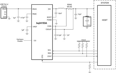
A host-controlled battery-charging system is characterized by the method of communication established between the main processor (host) and the battery-charging subsystem. In today’s single-cell portable applications, the most common type of communication is I2C. The host uses this communication channel to set the charging parameters and other system-level parameters, such as input current limits and VIN-DPM thresholds. In addition, the same communication channel is used to collect information about the status of the battery-charging subsystem. Figure 2 shows an example of an I2 C programmable battery-charging subsystem.

Fig. 2: TI’s BQ24153A, an I2 C programmable battery charger circuit.
In this circuit, charge current, charge voltage, input current, VIN dynamic power management thresholds and other parameters are adjustable through I2 C. This configuration allows for maximum flexibility for product design. The following sections will go over real design situations and how I2 C programmable chargers can help solve these problems.
JEITA battery-charging requirement
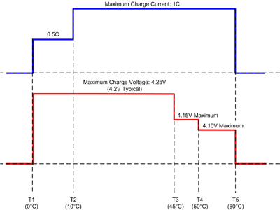
JEITA (JIS8712 and JIS8714) is becoming more popular across different regions for safely charging Li-ion batteries. Figure 3 shows the typical battery-charging requirements in order to be JEITA compliant.

Fig. 3: The typical battery-charging requirements necessary to be JEITA compliant.
In order to meet the JEITA requirements, charge voltage and charge currents need to be adjusted based on the battery temperature. In the case of a standalone design, a JEITA enabled battery charger needs to be used. However, there are limitations on these battery chargers. One of these limitations will be the beta and value of the thermistor. If the beta or the value of the thermistor is not a fit to the battery charger JEITA measurements, inaccuracies will occur and the temperature may not meet the JEITA requirements. Another limitation is the battery specification. In some occasions, the battery manufacturer will require a battery charge current of less than 50% of the rated capacity value when the temperature is between 0 and 10C. If this is the case, extra resistors and GPIOs are needed to modify the charge current based on the battery temperature.
One way of solving these limitations is to use an I2 C programmable battery charger. In this configuration, the host can measure the battery temperature and adjust the charge voltage and charge current based on the temperature measurement. No other BOM modifications are needed in order to meet the requirement. In addition, multiple battery vendors can be used even if the battery specifications are different, since the host always has the ability to adjust the charge parameters based on the temperature.
Standards are always changing and in many occasions, new standards are introduced for different markets. The use of flexible I2 C programmable chargers increases the probability of being able to meet new standards by only modifying software to meet the new requirements without having to re-design the battery-charging system.
Different types of batteries
Another typical problem encountered during the design of a system is the need of supporting different types of batteries. The batteries can have different chemistries, capacities or manufacturers. Using an I2 C programmable charger allows the use of the same battery-charging circuit with only software modifications in order to meet the requirements of the different types of batteries.
During product design, manufacturers need to validate their circuit design and software before a product is released. The advantage of using programmable chargers is that the charging circuit can be validated once during the initial development and only the software will need to be validated in future designs. This allows faster development cycles for the manufacturer.
Typical standalone battery chargers can only support battery chemistries that follow the same charge cycle profile. In a programmable battery charger, the host can modify the charge cycle to meet different types of battery chemistries. One example is the increasingly popular LiFePO4 battery chemistry. This battery chemistry uses a charge profile similar to the Li-ion charge profile.
However, charge termination is done slightly different and at a lower battery voltage. Using a programmable charger allows the designer to use the same battery-charging circuit and only modify the charge parameters in order to charge a LiFePO4 battery. In essence, an I2 C programmable battery charger allows the user to charge almost every lithium-based battery due to the flexibility of programming different charging parameters.
Input voltage dynamic power management (VIN-DPM)
Another typical use case in real world design is the need to support multiple types of input sources. With the increased popularity of the Micro-USB connector as a power input on products, designs are exposed to multiple power sources with different current capabilities. The battery charger is typically the first circuit to connect to this input power source, and the ability of having programmable input currents and VIN-DPM thresholds gives designers multiple options to easily meet the requirements of these different types of input sources.
One example is a product that uses a standard micro-USB connector. Using this connector allows the user to connect the product to a USB plug on a computer or to one of the many wall warts available that have this kind of connector. The USB plug on a computer supports 100 and 500 mA (USB2.0 current limits). However, a wall wart could have different kinds of current capabilities, as the micro-USB connector can support up to 1.8-A current. The circuit shown in Fig. 2 supports the USB 100-mA and USB 500-mA current limits, and these can be programmable through I2 C when the device is in host mode (I2 C enabled). In default mode (no I2 C communications, perhaps due to a depleted battery), the input current limit can be controlled by using an USB-PHY to control the OTG pin to set USB 100-mA or USB 500-mA modes. These two options make it easy for a designer to meet the USB current specifications. However, in the case of a wall wart with unknown current capability, more options are needed.
The circuit shown in Fig. 2 is for TI’s BQ24153A battery charger, which includes a feature called input voltage dynamic power management (VIN-DPM). This feature monitors the input voltage to the charger IC and maintains the programmed voltage in case the charging circuit demands currents greater than the adapter capability. This feature allows designers to program a VIN-DPM threshold that provides enough headroom for a battery to be completely charged.
For example, let’s assume that the total voltage drop from the input due to the charger IC, connectors, sense resistor and inductor is 300 mV for a given charge current. This means that the input voltage will have to be at least 4.5 V in order to be able to charge the battery.
Through I2 C, the host can select a VIN-DPM of 4.6 V (100 mV to account for tolerances), and the charger regulates the charge current to the programmed threshold as long as the input voltage stays above the programmed VIN-DPM threshold. If the input voltage drops to the VIN-DPM threshold, the charger reduces the charge current to the level that prevents the input voltage from collapsing, providing the user with a better experience by allowing them to charge from any wall wart they may have from other products.
Standalone battery-charging design provides a simple way of implementing a charging circuit. This design architecture requires no or very little software development in order to be able to charge the battery. The limitation is the lack of flexibility in the case where more complex requirements such as multiple chemistries, battery capacities or JEITA need to be met. I2 C programmable chargers provide a flexible and very efficient way of meeting these complex system-level requirements using software control, allowing users in many cases to shorten their development time by validating the battery charge subsystem only during initial development. ■
About the author
Miguel Aguirre is the systems engineering manager for the battery charge management group at Texas Instruments. He has many years of experience with linear and switchmode battery chargers. He can be reached at
.
Advertisement
Learn more about Texas Instruments


