BY JOEL WOODWARD,
Senior Product Manager,
Keysight Technologies*,
www.keysight.com
In today’s electronic designs, power distribution networks (PDNs) have become a key focus for several reasons. For one, the rails now provide lower voltages with tighter tolerances. Rails that were 5 V with 5% tolerance are shrinking to 1.2 V with a 1% tolerance. So designers must now measure signal details just a few millivolts in height. And PDNs may have 10 to 30 power rails. While some are copies, others have unique voltages; rail values can be as low as several hundred millivolts or exceed 10 V.
Another key reason is that power systems are becoming a key source of system jitter. Since PDNs are routed to all devices that need power, any noise or transients on power rails propagate throughout the system. In fact, noise and coupling on power rails is often the number one source of system jitter. So solving system issues requires more attention to the PDN.
To fully and accurately characterize PDNs, you need measurement tools that don’t change the behavior of power rails, and have adequate bandwidth to see periodic and random disturbances. Power integrity measurements — such as measuring ripple, noise, and finding sources of transient and period disturbances — have become much tougher. It’s impossible to see whether lower-voltage power rails are within tighter tolerances if the measurement is obscured by oscilloscope and probe noise. Getting adequate offset that allows teams to zoom in is problematic, and connection methods can inadvertently change dc voltage values.
The industry is now seeing probes specifically designed for power-rail measurements. Coupled with low-noise scopes with bandwidth limiting capabilities, engineers can be equipped to make dramatically more accurate power-integrity measurements. In the following paragraphs, we’ll provide four key tips for accurately testing PDNs with an oscilloscope.
1: Use instruments with the lowest noise
If your measurement is just a few millivolts, you clearly can’t afford several mV of measurement-system-induced noise. Periodic and random disturbances will get masked by the noise of the scope and probe.
The front end of all oscilloscopes generate some level of noise that gets added to the signal to be measured, and the trace you see on your scope’s display will be composed of both signal and noise from the scope. Since your scope’s 50-Ω path will have much lower noise than the 1-MΩ path, the 50-Ω path is a much better candidate for power-rail measurements.
At 1-GHz bandwidth, noise levels can vary about 100% between scopes with the lowest and the highest noise. While manufacturer’s datasheets for new oscilloscopes typically include sensitivity noise information, determining how much noise your scope has is easy.
To measure scope noise, disconnect all inputs and measure the Vrms or Vp-p at each vertical setting. (Engineers testing power rails often prefer a peak-to-peak noise measurement, as ripple and noise on the rail is typically measured using peak-to-peak values.) Repeat the noise measurement for each vertical sensitivity you’ll be using, then use the measurements to create a chart (fig. 1 ). For power-rail measurements, vertical settings of 50 mV/div or less are the ones that will typically be used.
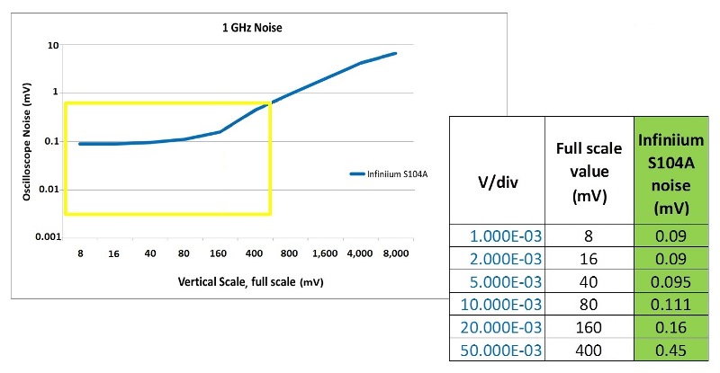
Fig. 1: Take a few minutes to characterize the noise on your scope. In the noise characterization of Keysight’s Infiniium S-Series at 1 GHz seen here, noise is reduced as the vertical setting is made more sensitive. So to limit the scope’s noise contribution, it’s best to use a vertical scale where the power rail takes up most of the scope’s display.
If you have the choice of two different scopes, use your results to determine which scope to use. Or if you are constrained to a specific scope, use measured noise values to determine which scope channel will be best. Noise will vary slightly from channel to channel at each vertical setting. You may be tempted to use oscilloscopes that have greater than 8 bits of ADC resolution. However, scope noise from the front end always plays a greater role than the resolution of the scope’s ADC, particularly at vertical sensitivities of 20 mV or less. Remember, it’s not the resolution but the noise that matters.
In addition to noise induced by an oscilloscope, attached probes or cable will add incremental noise. Probes that have lower attenuation ratios, like 1:1, will have lower noise than probes with 10:1 attenuation ratios, and thus lower attenuation ratios are preferred for power-rail measurements. Fig. 2 shows an example of two probes, each connected to the same scope. One probe adds very little noise on top of the scope noise, while the other probe increases overall noise by 10 times.

Fig. 2: Probe noise adds to oscilloscope noise. As seen in the scope screen capture of noise from two different probes that could be used for power rail measurements, the Tektronix P6248 probe has more than 10 times the noise of the Keysight 7020 power-rail probe.
To test probe noise, connect the probe to the oscilloscope channel you will be using. Then connect the probe tip to ground and measure Vrms or Vp-p . This is the noise of both the oscilloscope and the probe. Oscilloscope manufacturers don’t usually publish probe noise, so you may need to ask for a loaner and run this quick experiment.
Selecting a probe with low noise is even more important than selecting an oscilloscope with low noise. Probes typically contribute much more noise than the oscilloscope. However, low-noise probes are becoming available. For example, Keysight’s N7020A power rail probe adds little noise; when connected to an Infiniium oscilloscope, it increases total scope system noise by only 10%.
2: Employ noise-reduction techniques
The biggest contributor to noise within a specific scope is broadband noise. Disconnect all inputs to your scope and then turn on the scope’s FFT function to see the resulting noise in the frequency domain. For instance, the FFT for an Infiniium S-Series oscilloscope with 4-GHz bandwidth shows consistent noise density all the way out to the bandwidth of the scope. Integrate the area under the FFT, and you’ll get the same noise value that you see in the time domain.
Turning on bandwidth filters/limiters lets users reduce broadband noise and get a more accurate measurement. So if your measurements don’t require the scope’s full bandwidth, bandwidth limit as much as possible. But there’s a caveat with bandwidth limiting: you need to ensure that you don’t limit too much. For example, if you use a probe that has 35 MHz bandwidth, you won’t be able to see disturbances or crosstalk from sources that have frequency components above 35 MHz (fig. 3 ). While ripple typically has frequencies in the kHz range, periodic distortion from coupled sources and fast edges can have tones in excess of 1 GHz.
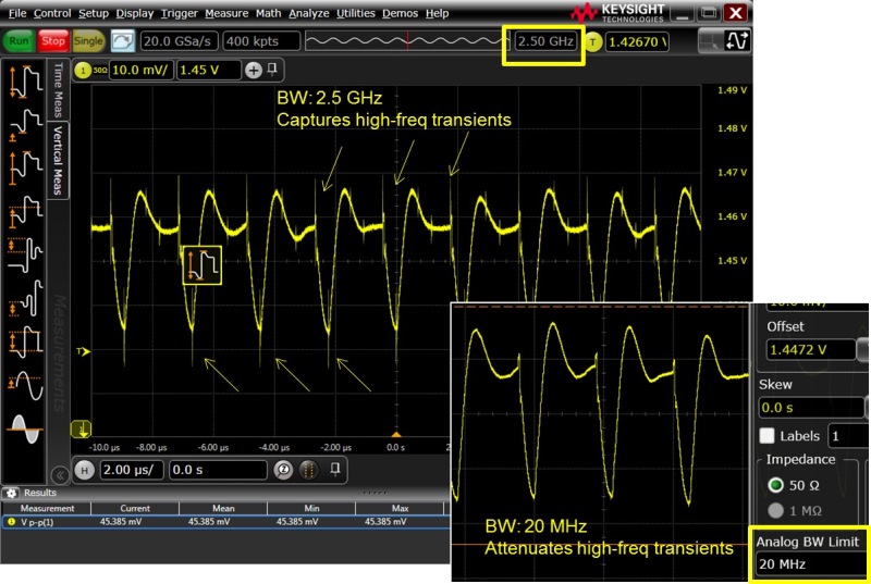
Fig. 3: Comparing power-rail measurements with different bandwidth limits makes clear what impact over-limiting can have. The high-frequency disturbances that can be seen clearly with a 2.5-GHz bandwidth (main image) become invisible when 20-MHz bandwidth limiting is turned on (inset).
A second method of noise reduction is less obvious, but just as important. As previously discussed, noise is a function not only of bandwidth but of vertical sensitivity of the scope as well; noise is reduced as vertical sensitivity is lowered. For example, on Keysight’s 1-GHz S-Series oscilloscopes, noise is 450 µV at 50 mV/div, 160 µV at 20 mV/div, and just 90 µV at 2 mV/div. The key here is to use the sensitivity that results in the highest signal-to-noise ratio; that is, you want to scale your power rail to take up most of the scope’s vertical range.
If you need to look at two power rails simultaneously, stacking them (where each takes up one half of the oscilloscope grid) will result in more noise. For a more accurate measurement with lower noise, place each in its own grid with a smaller vertical setting.
3: Choose a probe that provides offset
Measuring power rails requires that users place the rail voltage midway between the top and bottom of the oscilloscope’s display, and then zoom in to measure ripple and see transients. But typically, an oscilloscope's offset is a function of vertical scaling. So the built-in offset is often not sufficient when zooming in using small vertical gains.
For example, on Infiniium S-Series scopes, available offset is only 24 mV when zoomed in at 10 mV per division. (You’ll find that this to be the case with most scopes.) This makes it impossible to zoom in on power rails of 3.3 V, 1.6 V, or similar voltages.
There are a two workarounds to address this challenge. Many engineers choose to use a blocking capacitor to eliminate the dc voltage; this approach works in the sense that it allows users to see just the ac component of the signal. However, one major tradeoff is that this approach eliminates the ability to see dc drift and sag. Such dc values can change as devices are turned on and off, and knowing the dc value in addition to ac characteristics is critical. For this reason, the use of blocking caps is typically not desired.
A better technique to achieve required offset is to use a probe with offset. Probe manufacturers often design offset capabilities into probes to allow them to compensate for limited offset in the scope. For the previously mentioned example, where the oscilloscope only offered ± 24 mV of offset, the addition of a power-rail probe such as the N7020A makes a ±24V offset available! This offset range covers most power rail dc values and allows user to zoom in down to 1 mV/div with no additional offset restrictions.
4: Use a probe with large input impedance
Should you directly connect a coax cable to the scope’s 50-Ω input, or use a probe? The answer is related to the input impedance of the connection methods. Power rails typically have impedance of less than 1 Ω. When users connect a 50-Ω coax between the scope and the power rail, two things will happen. First, the 50-Ω connection creates a resistor divider network. Some of the current (roughly 2%) will now flow through the coax to the scope and be sucked away from the target system. Second, the scope will now measure a dc value smaller than what the original dc value was before the addition of the 50 Ω input impedance; that is, it will provide inaccurate dc measurements. It’s also the reason that, even if your oscilloscope has enough offset built in, it’s more advantageous to use a high-impedance probe with offset.
Probes designed specifically for power rail measurements are beginning to emerge. Their design tradeoffs target attributes that will produce the most accurate power rail measurements. These attributes include low noise (and associated 1:1 attenuation ratios), high offset ranges, high input impedance at dc, and adequate bandwidth to see transients. Keysight’s N7020A power rail probe is an example; it has an input impedance of 50 kΩ at dc, so it will impact loading a thousand times less than using a 50-Ω coax directly into the 50-Ω scope input.
* Keysight Technologies was formerly Agilent Technologies' electronic measurement business.
Advertisement
Learn more about Keysight Technologies, Inc.


