BY CHANCE DUNLAP, Marketing Manager for Infrastructure Power Products , Intersil, www.intersil.com
Digital power can reduce power consumption and manage the growing power complexity in modern electronic systems and in smart handheld or portable consumer electronics products. Digital power management and control provide real-time intelligence that enables system developers to build power systems that automatically adapt to their environment and optimize efficiency. The use of intelligent digital power ICs means automatic compensation for changes in load and system temperature, enabling energy savings with adaptive dead-time control, dynamic voltage scaling, frequency shifting, phase dropping, and discontinuous switching modes.
The power supply’s ability to enable these modes to optimize system efficiency is a major benefit. Managing power means managing voltage and current monitoring, voltage sequencing, voltage tracking, fault detection and fault management. Thermal management includes monitoring temperature throughout a system and responding to conditions by controlling fans or shutting down parts of the system. Also important: integrating the power and thermal management with the power conversion, which removes the need for added power and thermal management ICs.
Design flexibility
A complex yet reliable power distribution system requires many voltage rails, which are required to sequence or track other rails to properly bias microprocessors, microcontrollers, ASICs, FPGAs, and any other digital logic ICs in the system, and which likely require differing voltages for operation. As a product design moves through various phases, changes can occur including the addition of a power rail, more current on a rail, or the requirement for a tighter transient response. Normally, this would require the redesign of the power distribution. But a digital power solution can adapt with changing requirements. A new voltage rail can be added to the power-management system using the industry-standard System Management Bus (SMBus). The digital power ICs communicate via the SMBus using the Power Management Bus (PMBus) protocol, the standard protocol for communicating with power conversion systems using a digital communications bus. Using PMBus and PMBus-enabled devices for power conversion provides flexibility and control not possible with traditional analog power systems. Adding a new rail is integrated into the monitoring, sequencing, margining, and fault detection schemes. The digital power IC for the new rail is provided with its own SMBus address and is added to the system. There is no need to reprogram or add more stand-alone power-management ICs because of the additional voltage rail.
In addition, for system monitoring, a digital power solution provides multiple methods of reacting to a fault. Overcurrent and undercurrent, overvoltage and undervoltage, and overtemperature faults and warning thresholds can be configured and adjusted throughout product lifecycles. Digital power solutions reduce cost — the lower component count makes a more reliable and longer-lived system, and enables designers to use the same device for each voltage rail and make changes to the operation of the device without costly hardware alterations. Digital power solutions meet increasingly tough thermal demands, a challenge as boards become denser and generate more heat.
New digital power platform
One of the major challenges with analog power is that engineers have to work within the “poles and zeros” of the frequency domain to maintain device stability. The new ZL8800 offers a fully digital compensation-free control loop — if an event occurs in a system and the output capacitance is changing dynamically, the device will continue to remain stable, while delivering a faster transient response than is achievable with an analog control loop. This advanced compensation loop technology, coupled with state-of-the-art silicon power IC design and an intuitive easy-to-use GUI-based software, delivers a complete system overview for power system architects and designers.
Based on Intersil Zilker Labs Digital-DC technology, the ZL8800 dual-channel dual-phase controller integrates a high-performance step-down converter for a wide variety of power supply applications. The device provides best-in-class transient response for digital point-of-load (POL) converters, saving on output capacitors and board space. Designed for use in advanced power systems found in the latest generation of base stations, routers, and other data-communications infrastructure designs, the device enables designers to fully control and monitor, via the PMBus interface, every power rail to maximize reliability, and use monitors and sequencers to provide added functionality around the POL converters. Intersil’s proprietary single-wire DDC (Digital-DC) serial bus also enables the ZL8800 to communicate between other Zilker Labs ICs. By using the DDC, the ZL8800 achieves complex functions such as inter-IC phase-current balancing, sequencing, and fault spreading, eliminating complicated power supply managers with numerous external discrete components.
Fast transient response without the need for loop compensation is a major advantage for designer because it can achieve precise control of the complete power conversion process without the need for software, resulting in a flexible and easy to use devices. The ZL8800’s architecture enables this fast transient response without loop compensation. Adaptive algorithms enable the power converter to automatically change the operating state to increase efficiency and overall performance with no user interaction needed.
Power management functions are fully integrated and can be configured using simple pin connections. The user configuration can be saved in internal nonvolatile flash memory. Additionally, all functions can be configured and monitored via the SMBus hardware interface using standard PMBus commands, with no programming required. Advanced configuration options and real- time configuration changes are available via PMBus commands, and continuous monitoring of multiple operating parameters is possible with minimal interaction from a host controller. Integrated sub-regulation circuitry enables single supply operation from any power supply between 4.5 and 14 V without the requirement for bias supplies.
Maximum loop response
Traditionally, voltage- or current-mode hysteretic controllers have offered the best loop response, but these come with the drawback of switching with variable frequencies. Modern telecommunication equipment that uses digital power controllers requires fixed-frequency operation, allowing tight control of the noise spectrum in end-user applications. Reacting to voltage deviation in a single PWN switching cycle is a significant advantage. The ZL8800’s proprietary digital modulation technology, ChargeMode control, features a digital modulator and compensation technique in a digital modulation technology, so the controller can react within the single switching cycle. ChargeMode control is digital voltage-mode control with the ability to achieve high bandwidth using the single cycle response technology. One switching cycle represents the smallest quantum of control in a PWM and represents the upper limit in terms of speed in responding to a transient.
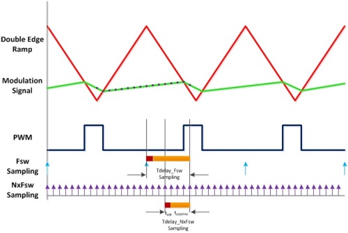
In addition, digital PWM controllers typically are uniformly sampled — the controller samples error and compute the modulation signal once per switching cycle. This can introduce latency or group delay, a significant portion of the switching cycle. The group delay translates to phase lag, which increases with frequency and places an upper bound on the achievable closed-loop bandwidth. In contrast, the ZL8800 uses a mixture of uniform and multi-rate sampling techniques, which samples the error and computes the modulation signal multiple times during a switching period, reducing group delay and supporting very high bandwidth operation.
Figure 1 shows ZL8800’s sampling technique. The total delay (tdelay) is the sum of ADC conversion delay and computation delay (including pipeline/filter delays). Fig. 1 also clearly demonstrates the reduction of tdelay in the ZL8800 compared to a uniformly sampled PWM modulator.
The ZL8800 digital compensator processes the quantized error signal and generates duty cycle command for the PWM modulator. The control loop is designed to react to a voltage deviation in a single cycle. This can be achieved by a proportionate gain that is linear to the error voltage deviation. By using only a proportionate gain it is possible to achieve single cycle reaction using fixed-frequency switching but it does not guarantee stability. The controller knows what is done to the duty cycle in one cycle and attempts to localize its effect to one or a few cycles. If the duty-cycle effect propagates to the next few cycles, then it may lead to the point of instability. What is done to the duty cycle within the ZL8800 to correct for a voltage deviation in one switching cycle is undone within the next switching cycle or next few cycles, hence ASCR (a single cycle response).

Fig. 1: ZL8800 digital PWM modulation.
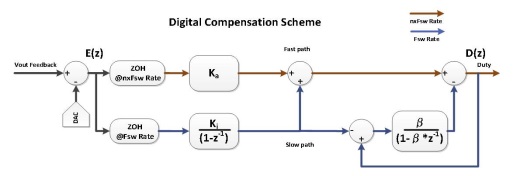
The compensator block diagram (see Fig. 2) has many similarities to a traditional digital PID (proportional-integral-derivative) controller, but it also has significant differences. The diagram indicates how the multi-rate sampling technique is integrated within the compensator. The compensator has two parallel paths for processing the quantized error voltage. One is called the ‘fast path,’ which samples error voltage more frequently than the ‘slow path.’ In this unique compensator structure, the duty cycle command is fed back to determine the effect of the fast path and to nullify the fast path effect in the following cycles.

Fig. 2: ASCR digital compensator.
The fast path consists of the proportional gain (ASCR gain) Ka, in Fig. 2, which samples the error and processes the duty cycle at NxFsw (N times the switching frequency rate). The slow path samples error at Fsw rate and processes duty cycle only once per switching cycle. The fast path responds to voltage deviation in proportion to the error voltage. The slow path consists of the Integrator function, with Ki as its gain, used for low frequency gain and duty cycle reset function with β as its gain. The duty cycle reset function nullifies the effect of the fast path during a transient event as it feeds back the duty cycle change due to fast path and also the steady-state duty cycle from the integral function. The z-domain or frequency-domain transfer function is shown in Fig. 3 . The compensator simplifies down to a two-pole, two-zero filter, which enables the stability of the closed-loop system.

Fig 3: Digital compensator z-domain.
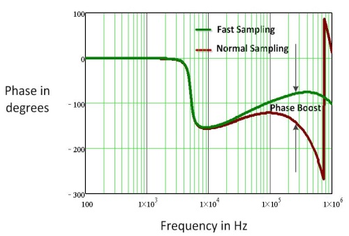
The ZL8800 compensator structure has reduced delays between the error-sampling instant and the duty cycle decision. This translates to a natural phase boost at high frequencies, which brings stability and makes it possible for high-bandwidth designs (see Fig. 4 ).

Fig. 4: Phase boost at high frequencies.
Thus the ASCR compensator can achieve an inherently stable control loop, which only needs to be tuned for bandwidth specification. In a wide range of output filter configurations, only ASCR gain needs to be varied to reach the desired closed-loop bandwidth operation. In fact, there are actually two inputs to the ASCR block: gain setting and a residual. Gain sets up the overall transient response speed, whereas the residual is a dampening factor, essentially setting the response rate of the loop, which could be important to bring out the last ounce of performance. However, the ZL8800 default setting for the residual value will be suitable for most systems.
The major drawback of multi-rate sampling technique is the injection of switching frequency harmonics into the feedback loop due to over sampling of the error. In the ZL8800, a low-latency ripple filter is engaged in the fast path, so that all the repetitive elements of ripple are totally rejected. All that remains are the nonperiodic elements in the waveform including transient steps with little or no delay, resulting in more than 20 dB of ripple reduction without a significant time delay, allowing high gains and higher bandwidths.
PowerNavigator software and evaluation boards
The remaining element that ties the Intersil approach together is the company’s PowerNavigator software. While some advanced power systems may require extensive programming and coding experience from users to set up the commands and functionality required to access the capabilities of digital power management devices, PowerNavigator enables the simple configuration and monitoring of multiple Intersil digital-dc devices using a PC or Mac via the USB interface. The tool makes it easy to change all features and functions of a digital power supply design using a simple graphical user interface. Through simple drag-and-drop graphics users can simplify and create an entire power management environment without having to write a single line of code.
Advertisement
Learn more about Intersil


