Lighting-emitting diodes (LED) pervade nearly every electrically operated device, broadly serving functions ranging from power-status display to general illumination. With continuing advances in their capabilities and characteristics, LEDs have emerged as the dominant light source not only in electronic equipment but also replacing traditional incandescent and fluorescent lamps in every conceivable application.
Electrically, an LED is simply a semiconductor diode comprising a p-n junction where the p side, or anode, contains excess positive charge (holes) and the n side, or cathode, contains excess negative charge (electrons). The application of a forward voltage across the p-n junction causes electrons to move from the n area toward the p area and holes to move toward the n area. Near the junction, the electrons and holes combine with the release of energy as photons, resulting in the light emitted by the LED.
LEDs offer a number of advantages to application developers in general and circuit designers in particular. While traditional light sources release photons in all directions and at broad wavelengths, LEDs provide highly directional illumination at relatively narrow wavelengths determined by the type of semiconductor material used in constructing the p-n junction. LEDs are also much faster than traditional light sources — able to turn on and off instantly, requiring no warm up time. In fact, LEDs can be switched rapidly and indefinitely with little or no impact on device lifetime. LEDs operate in a wide range of temperatures and even offer improved characteristics at lower temperatures. Mechanically, LEDs are small, compact, and robust devices that can be used reliably in tight or harsh environments where traditional illumination could not fit or even survive.
With continued advances in LED fabrication technology, these devices have evolved significantly from the familiar 5-mm red bulb to sophisticated lighting sources (Fig 1). As semiconductor devices, all LEDs — from simple 5 mm to advanced high powered devices — can be designed simply into any circuit and controlled like any other electronic device. Indeed, working with LEDs means designing them into circuits with the same attention to operating requirements and datasheet specifications given to any electronic part.
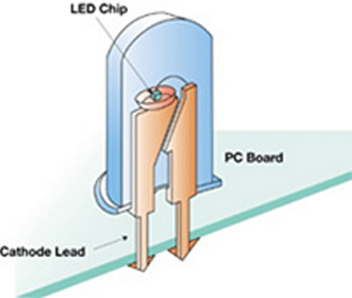
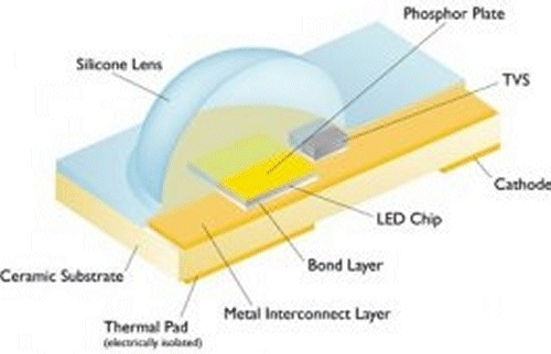
Fig. 1: Advances in semiconductor fabrication technology enable a range of LEDs from a simple 5-mm LED (top) for traditional indicator display applications to high-powered devices (bottom) designed for illumination applications. (Source: Philips)
Two of the most important operating parameters in dealing with LEDs are forward voltage (VF) and forward current (IF). LEDs are low-voltage devices, typically requiring VF below 5 V and IF ranging from the tens of milliamps for small indicator devices and hundreds of milliamps for illumination-grade LEDs. LEDs are very sensitive to applied voltage. Small changes in VF result in large changes in IF (Fig 2) Excessive forward current and small reverse voltages can destroy the device. Consequently, one of the most important specs in an LED datasheet is its absolute maximum forward current. LEDs need to be driven at their nominal IF specification to achieve specified performance.
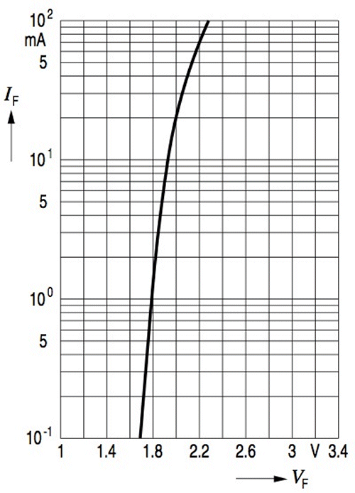
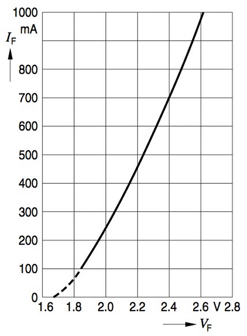
Fig. 2: Small changes in forward voltage VF result in large changes in forward current IF in any LED, although maximum IF values in a conventional display LED (top) are substantially lower than those for a high-powered illumination-grade LED (bottom). (Source: Osram)
In its simplest form, a LED driving circuit needs only a current limiting resistor, or ballast (Fig 3). Despite the obvious advantages in simplicity and cost, this approach results in power inefficiency from the loss across the series resistor and lacks the flexibility to maintain light intensity with changes in the operating environment or circuit characteristics.
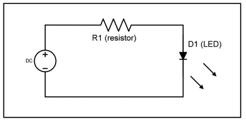
Fig. 3: Simple LED driving circuit using a current limiting resistor. (Source: Osram)
Indeed, LED light output is highly sensitive to forward current (Fig 4) and temperature (Fig 5). Engineers can address these problems through commercial LED driver ICs and temperature-compensation methods. Perhaps one of the most flexible methods for controlling LEDs is the use of pulse-width modulation (PWM) driving current, where LED intensity is controlled by varying the duty cycle of the current source. LED manufacturers will often provide performance charts showing current-pulse characteristics well above the maximum forward current rating.
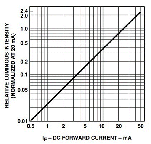
Fig. 4: LEDs require constant current because variations in current result in variations in light output. (Source Avago Technologies)
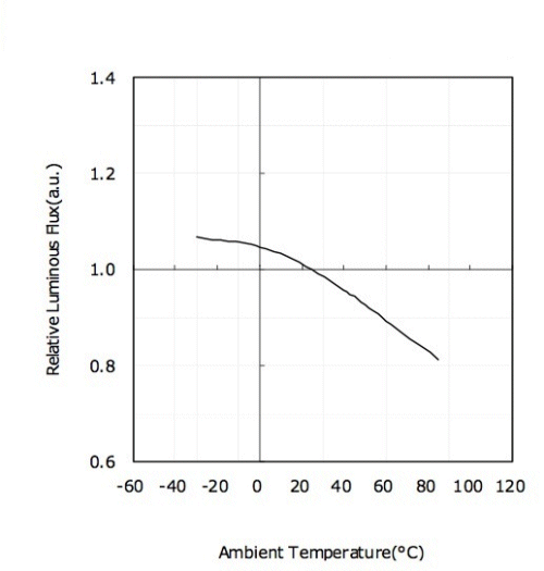
Fig. 5: Thermal management is critical in LED design because variations in temperature result in variations in light output. (Source: Nichia)
For most engineers, LED specifications introduce new and unfamiliar characteristics related to the light-producing capabilities and color of the device. As LEDs have moved beyond their early days as simple indicator displays, lighting engineers have required detail about LED characteristics beyond more self-explanatory datasheet parameters such as dominant wavelength and luminous flux. One such characteristic is luminous efficacy. Not to be confused with LED efficiency (a measure of how well the LED structure emits the photons it produces), luminous efficacy describes how effectively the device converts power to light and is provided in lumens/Watt.
Beyond these straightforward performance parameters, however, datasheets for state-of-the-art LEDs include extensive tables and graphs for key color parameters including correlated color temperature (CCT), color rendering index (CRI) and chromaticity coordinates — standardized values intended to provide a normalized specification of how a human would perceive the color emitted by the device.
Measured in degrees Kelvin, CCT specifies the color appearance of a light source compared to a reference source heated to a particular temperature. Paradoxically, lower K ratings appear visually hotter. For example, visually harsh high-pressure sodium lights have a CCT of 1,900 K while so-called “cool white” fluorescent lamps have a CCT of 4,200 K.
CRI represents how well the light source renders colors compared to standard incandescent and daylight reference sources. High-pressure sodium lights typically have a 22 CRI, while a cool white fluorescent lamp has a CRI around 62. For interior lighting applications, industry and government groups recommend a minimum CRI of 80. Because advances in LED technology have made such comparison increasingly difficult, an alternative standard for color quality will eventually replace this parameter.
One of the most important color-related datasheet parameters is the chromaticity coordinate. Defined in 1931 by the International Commission for Illumination, or Commission Internationale de l’Eclairage (CIE), the CIE 1931 Chromaticity Diagram represents any color as a coordinate in a two-dimensional color map (Fig 6). Any point on this map specifies both the hue (specific color) and saturation (color purity) for a color. As a point nears the center of the map, it appears as an increasingly pure white light. LED manufacturers typically include x,y chromaticity coordinates in datasheet specifications. A popular variation of this diagram, CIE 1976, is an alternate mapping that appears as u',v' coordinates in datasheets.
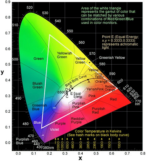
Fig. 6: LED datasheets typically list color (or color range) as one or more x,y coordinates on the CIE 1931 Chromaticity Diagram shown here. The white triangle illustrates the color gamut, or color range available through rgb color matching in LEDs. (Source: Ledtronics)
Practical applications of LEDs requires a careful understanding of the specifications for the particular device of interest — and an appreciation that each device will exhibit variations in behavior from even the stated specs. By careful analysis and adherence to LED datasheet specifications, engineers can incorporate more advanced LEDs into a growing array of applications. ■
Advertisement
Learn more about Electronic Products Magazine


