Here are the basic battery and charging concepts to understand when using the very popular Li-based batteries
BY GEORGE PAPARRIZOS
Summit Microelectronics
www.summitmicro.com
The most popular battery type in modern consumer electronics is the Lithium-ion type. There are many advantages of this battery technology versus other rechargeable ones, like higher energy density, lower discharge rate, better environmental properties and higher operating voltage. Over the last few years, some varieties of this battery technology have also evolved to address issues such as form factor, reliability and operating life. Among these new Li+ variations, lithium polymer has been the one to be very widely adopted by the marketplace, primarily because of its form factor flexibility. The new batteries and their corresponding performance are the result of changes in the material properties, more specifically of the battery’s anode, cathode and electrolyte.
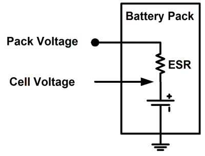
Figure 1 shows a simplified block diagram of a typical battery pack. It consists of the main battery cell and an equivalent series resistance (ESR). The internal impedance of a battery is dependent on the specific battery’s size, chemical properties, age, temperature and the discharge current. Hence, the voltage measured at the terminals of the battery is the sum of the voltage drop across the ESR and the battery cell voltage. Given the sensitivity of this Li-ion and Li-polymer batteries, battery packs are required to include protection circuitry to prevent runaway events. These safety electronics ensure that the cell is not exposed to over-/under-voltage and/or over-current situations.

Fig. 1: Battery equivalent circuit
Battery capacity
Battery capacities are described in terms of mAh or Ah. Small handheld devices, like headsets, use batteries with capacities as low as 80 mAh, whereas smartphones usually require batteries as large as 1,800 mAH. Charging rate is defined as C or C-rate and indicates a charge or discharge rate equal to the capacity of a battery in one hour. As an example, a 0.1C charging rate of a 1,500 mAh battery is 150 mA. As will be discussed below, the recommended charging rate for a battery during the different charging phases is based on the battery manufacturer’s recommendations (battery datasheet), and is usually dependent on the targeted battery cycle life. Deviation from the datasheet specifications is not recommended, since it could lead to early battery degradation.
The average and peak power requirements of the application, in combination with an acceptable usable battery life will determine the necessary battery capacity. Choosing a specific battery capacity and form factor can result in significantly lower cost if the same battery type is widely adopted in high-volume portable applications. While higher battery capacity ensures longer operating life, it also translates to larger weight and longer charging time. Therefore it is critical to carefully weigh all the tradeoffs (system run time, form factor, weight, charging time) before selecting the corresponding battery pack.
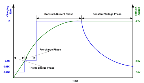
The charging for Li-based battery packs follows a specific algorithm and can be divided to four phases, as also shown in Fig. 2 . When the battery is deeply discharged (typically below 2.0 V) a small current is provided to the battery to enable the reactivation of the internal protection FETs which have opened due to an under-voltage condition. This trickle-charge current is usually kept below 30 mA to ensure charging the battery while keeping power dissipation inside the battery pack to a minimum. Once the battery voltage crosses the deeply-discharge level, charging enters the precharging phase in which the current level is usually set to 0.1C. Precharging continues until the pre-to-fast charge voltage threshold is reached, a threshold that is usually recommended by the battery manufacturer (commonly between 2.6 and 3.0 V). The next phase is the constant current one, in which a fast charge is applied to the battery. Once the battery voltage reaches its float voltage level (in most modern batteries this is 4.2 V), charging enters the constant voltage phase and charge current starts diminishing. In theory, the battery cell is not fully charged until the cell voltage is 4.2 V with very little current going into the battery, which would mean that the voltage drop across the ESR is negligible.

Fig. 2: Typical charging profile (not to scale)
Charging
The charging process is usually suspended in two different ways: a) charge current has reached the current termination level or b) safety timers have expired. The first way is the normal one for suspending charging and while a very common setting is 0.1C, many system designs select a lower level, like 0.05C. The tradeoff between terminating charge sooner (higher current termination level) or later (lower termination level) is the compromise between charging time and battery capacity at the end of the charge cycle. Charge termination via safety timers is usually used only as a backup, in case a defective battery cell takes a very long time to charge.

Fig. 3: Simplified battery-charging system
While the battery pack in use determines the theoretical charge current required for the battery during the different charging phases, system engineers need to also consider two additional factors that affect the actual charge current levels and should be taken into account when designing the charging subsystem. The first one is the current capability of the input power source, which in most cases is a wall adapter or a PC USB port. Naturally, the higher the current going into the charging circuitry from the power source, the higher the current going into the battery will be. The second factor that may have an effect in the actual charge current level is the operating state of the system during the charging process. When the portable device is in active mode during battery charging (that is, the system is running), it will consume part of the current provided by the power source, and therefore the current going into the battery will be lower than the theoretical value. ■
Related Products: Batteries
Advertisement
Learn more about Summit Microelectronics


