Contributing Editor
Temperature measurement is fundamental to electronic design in general and semiconductor performance in particular. For engineers, an understanding of temperature sensor capabilities and limitations is vital for ensuring the kind of accurate measurement required to achieve expected operating characteristics in electronic designs.
Engineers can choose from a wide variety of temperature-sensing technologies including thermocouples, thermistors, RTDs, and IC sensors. Each type is best suited to a particular temperature range, operating characteristic, and final design cost. Despite significant differences in sensing characteristics, all non-IC temperature sensors including thermocouples, thermistors, and RTDs share certain common electrical characteristics. These discrete temperature sensors provide very small signal, non-linear outputs and require a signal chain capable of amplifying and correcting these signals despite the presence of noise (Figure 1).
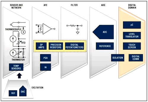
Fig. 1: Discrete temperature sensors are noisy, small-signal devices that require amplification, linearization, and calibration to ensure accuracy across the desired temperature-measurement range. (Source: Maxim Integrated Products.)
In the past, engineers have had to use precision components and manually calibrate the signal chain circuitry to achieve desired accuracy. Today, however, engineers can choose from a variety of temperature measurement ICs that combine analog front ends and signal processing capabilities — greatly simplifying the creation of very accurate temperature measurement designs. Building these designs, however, starts with selection of the transducer technology that is most appropriate for the specific application.
Thermocouples
Thermocouples are made by joining two different metals. The difference in properties at the junction between the two metals results in generation of a voltage that is proportional to the difference in temperature between the metal junction at the measurement point (hot junction) and a reference point (cold junction) (Figure 2). Cold junction compensation is the process of calculating the actual measured temperature at the point of interest based on ambient temperature and the temperature differential between the hot and cold junctions.
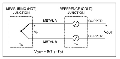
Fig. 2: A thermocouple produces a voltage that is proportional to the temperature difference between the hot (measurement) junction and cold (reference) junction, which is often a copper trace connecting the thermocouple leads. The Seebeck coefficient (“a”) specifies the relationship between temperature and voltage for different thermocouple materials. (Source: Maxim Integrated Products.)
Thermocouples are typically selected for their low cost, durability, relatively quick response time, and wide temperature range, which ranges from –300° to above 2,000°C depending on the choice of materials. The Instrument Society of America (ISA) designates thermocouple classes based on performance. ISA Type E, J, K and T are base-metal thermocouples with a temperature range from about -200°C to 1000°C. ISA Type S, R and B are noble-metal thermocouples with a temperature range from about –50° to 2,000°C.
Thermocouples generate very low voltage levels. For example, type K produces about 40μV per °C for type K. Different classes of thermocouples exhibit pronounced differences in changes in voltage with temperature (Fig. 3). Consequently, engineers should be careful in selecting a thermocouple that varies as little as possible over the anticipated temperature range of interest.
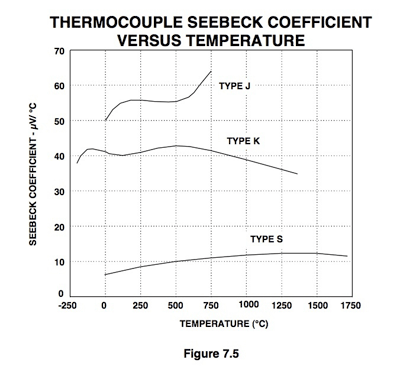
Fig. 3: In selecting thermocouples, engineers should look for the device Type that offers the greatest linearity across the desired operating range.
Source: Analog Devices
Thermistors
Built with semiconductor materials, thermistors are discrete devices whose resistance varies with temperature. Negative temperature coefficient (PTC) thermistors exhibit lower resistance with increasing temperatures, while resistance increases with temperature in positive temperature coefficient (PTC) (FIg. 4). Thermistors offer very high sensitivity to temperature changes, fast response time, and low cost. On the other hand, their response is highly non-linear and their operating range is typically limited to a much narrower range than thermocouples — in the range of –100°C to 150°C.
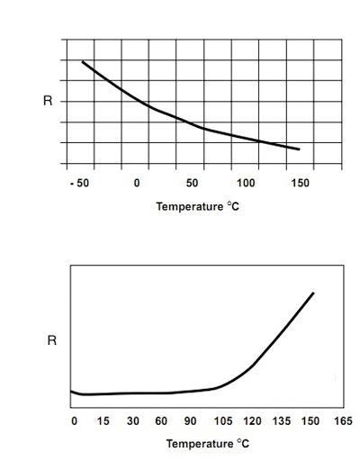
Fig. 4: Resistance decreases with increasing temperature in negative temperature coefficient (NTC) thermistors (top) and increases with temperature in positive temperature coefficient (PTC) resistors (bottom). (Source: Vishay.)
Resistance temperature devices
Like thermistors, Resistance Temperature Devices (RTDs) are resistors whose resistance varies with temperature. Unlike thermistors, RTDs are very accurate temperature sensors. In fact, RTDs are considered the standard for precision temperature measurement among discrete temperature sensors. Often made from platinum wire, RTDs operate in a wide temperature range (200° to 850°C) and offer very high repeatability, low drift, relatively good linearity, and high accuracy (Fig. 5). Depending on type, RTDs have an accuracy of between 0.03 and 0.3 °C.
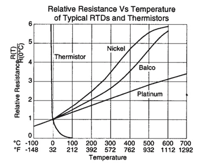
Fig. 5. Noted for their high accuracy, resistance temperature devices (RTDs), particularly the most commonly used platinum RTDs, offer good linearity and significantly broader temperature ranges than found in conventional thermistors. (Source: Honeywell.)
As passive components, both thermistors and RTDs require a current excitation source to measure change in resistance. In turn, measurement accuracy and repeatability depends on the use of a highly stable and accurately matched current source.
Engineers must also exercise care using current excitation with these devices, because current through these resistive devices generates heat. Self-heating changes the temperature of the temperature transducer itself and thus introduces measurement error. As a result, engineers should be careful in operating these devices within self-heating limits specified in manufacturer data sheets and typically provided for operation in both still and moving air. With their smaller thermal mass, thermistors and smaller RTDs can be particularly susceptible to this problem. As a result, engineers should use the smallest possible current and largest possible thermistor or RTD value required to achieve desired results at the same time balancing the fact that larger RTDs, for example, will result in slower response times.
IC temperature sensors
IC temperature sensors are typically offered as complete temperature measurement solutions, combining silicon-based sensing circuits with most or all of the remaining stages of the signal chain, including signal conditioning, comparators, and digital interfaces. Although these devices typically operate in a more limited temperature range, their inclusion of on-chip compensating features results in highly linear output, available as either analog or digital signals. Of course, additional on-chip features mean greater cost, which engineers must balance against simplified design and greater measurement accuracy.
This type of on-chip temperature sensing is routinely used in highly integrated digital devices such as CPUs and graphics processors. The very large gate count and high clock rate of these devices typically means high power consumption and accompanying thermal management concerns. The use of on-die temperature sensing helps ensure much higher accuracy and response time than possible with external sensing methods. Intel Core i5 processors, for example, include an on-chip diode used to monitor the die junction temperature. In operation, this internal thermal sensor will cause the processor to stop all execution when the junction temperature exceeds approximately 130°C. ■
Advertisement
Learn more about Electronic Products Magazine


