SyncE uses the physical layer interface to pass the timing from node to node
BY SLOBODAN MILIJEVIC
Zarlink Semiconductor
Ottawa, Ontario, Canada
http://www.zarlink.com
Over the last two decades Ethernet has become the dominant technology for data transmission. Due to its simplicity and low cost, it is also becoming popular with telecom and wireless providers for use in their networks.
However, the asynchronous nature of Ethernet provides certain challenges for transmission of time division multiplexing (TDM) services such as T1/E1 because they require clocks at the source and destination node to be synchronized with each other. Similarly, base stations in wireless networks need to be synchronized to a common clock for smooth call handoff between adjacent cells.
There are several ways to achieve synchronization over Ethernet. One method gaining momentum is synchronized Ethernet (SyncE). SyncE uses the physical layer interface to pass the timing from node to node in the same way timing is passed in SONET /SDH or T1/E1.
For telecom and wireless providers, this means that networks based on SyncE will be cost effective and as reliable as those based on SONET/SDH- and T1/E1. Ethernet equipment vendors are incorporating SyncE in hopes of getting a piece of a lucrative new market.
However, engineers working for Ethernet equipment vendors often lack previous exposure to synchronization and may underestimate the complexity of the issue by assuming that synchronization over Ethernet can be achieved merely by replacing the free-running crystal oscillator used for Ethernet PHY with a general-purpose synchronization device such as a phase-locked loop (PLL). Certainly, this is not the case and designs based on such an assumption are destined to fail.
Synchronization in telecom
Let us first examine why timing is important in telecom systems. Telecom systems are based on TDM (time division multiplexing; T1/E1 and SONET/SDH), which are best suited for transmission of constant bit rate traffic such as digitized voice and video. TDM technologies provide small transmission delay and small transmission delay variation — two key parameters for quality of voice and video transmission.
Small transmission delay can only be achieved if data buffering at each node is small. This implies that all nodes in a TDM based network must be tightly synchronized to a common clock in order to prevent data loss. If one of the nodes has a slightly different frequency, even for a short period, the buffer at that node will either overflow or underflow and the data sample(s) will be lost or repeated to keep the bit rate constant.
Traditional Ethernet vs. SyncE
Traditional Ethernet was intended for transmission of asynchronous data traffic and there was no need to pass the synchronization signal from the source to the destination. As a matter of fact, the old 10-Mbit/s (10Base-T) Ethernet cannot pass the synchronization signal over the physical layer interface because the 10Base-T transmitter stops sending pulses during idle periods—it sends a single pulse (“I am alive” pulse) every 16 ms to notify its presence to the receiving end.
Such infrequent pulses are not sufficient for clock recovery at the receiver. Idle periods in faster Ethernet flavors (100-Mbit/s, 1-Gbit/s, 10-Gbit/s) are continuously filled with pulse transitions, allowing continuous high-quality clock recovery at the receiver — good candidates for SyncE.
Let us review the operation of Gigabit Ethernet (GbE) over copper (1000Base-T) as shown in Fig. 1 . To reduce clutter, the figure shows each node with only two ports — although typically each has multiple ports.
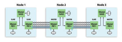
Fig. 1. Physical layer timing between nodes in traditional Ethernet uses a master/slave concept.
We have selected GbE over copper because it provides an additional challenge for SyncE implementation; one that does not exist in Ethernet over fiber. GbE over copper uses line coding as well as transmission over all four pairs of Cat-5 cable to compensate for the limited bandwidth of twisted pairs used in Cat-5 cables.
The transmission is done in both directions simultaneously, similar to ISDN and xDSL where DSP algorithms are used for echo cancellation. Echo cancellation is greatly simplified if the symbol rate is identical in both directions. This is accomplished with a GbE master/slave concept.
The master side generates a transmit clock locally from the free-running crystal oscillator and the slave side recovers the master clock from the received data and uses this to transmit its own data. The master and slave sides are determined during the auto-negotiation process. The master is generally assigned randomly using a seed value but it can also be set manually.
Synchronization does exist in Ethernet on each hop between two adjacent nodes, but it is not passed from hop to hop. In order to pass synchronization, we must take the recovered clock from the node receiving synchronization and then use this clock to feed all nodes that are transmitting synchronization as shown in Fig. 2 .

Fig. 2. Physical layer timing in SyncE sets up timing between nodes.
Of course, the recovered signal needs to be cleaned up to remove jitter generated from the clock recovery circuit with a PLL before being fed to the transmitting device. We also see that we need to manually set all ports in the clock path to alternate the master and slave function (only for 1000Base-T).
This is not an issue for GbE over fiber (1000Base-X) or for 10 GbE (10Gbase) because one fiber is always used for transmission and the other for reception—there is no bi-directional transmission on a single fiber. Therefore, there is no need for master and slave function.
Any Gigabit or 10-GbE PHY device should be able to support SyncE as long as it provides a recovered clock on one of the output pins. The recovered clock is cleaned by the PLL and fed to a 25-MHz crystal oscillator input pin on the PHY device.
Some newer Ethernet PHY devices provide a dedicated pin for the synchronization input. The advantage of this is that the input frequency can be higher than the 25 MHz — higher clock frequencies usually have lower jitter. This approach also avoids any potential timing loop problems within the PHY device.
SyncE requirements
From the discussion so far, it appears that the only requirement for a PLL used in SyncE is to clean jitter from the recovered clock, which can be accomplished with general-purpose PLLs. However, the PLL used in SyncE needs to provide some additional functions.
For example, if the receiving PHY device (Node 2, PHY 1 in Fig. 2) gets disconnected from the line, the recovered clock frequency will either stop or start to drift depending on the implementation of the clock recovery circuit. The general-purpose PLL will pass this big frequency change to the transmitting PHY device (Node 2, PHY 2 in Fig. 2).
As a result of this, not only is the transmission of synchronization signal going to fail but the data transmission could fail as well. The PLL used in SyncE must be able to detect failure of the recovered clock and switch the PLL to another good reference in the system or into holdover mode.
Requirements for SyncE are given in the timing characteristics of synchronous Ethernet equipment clock (ITU G.8262/Y1362) specifications. These specifications are based on ITU-T G.813 specification for SDH clocks. The major requirements are listed below:
Free run accuracy . The accuracy of PLL output when it is not driven by a reference should be equal or better than ±4.6 ppm (part per million) over a time period of one year. This is a very accurate clock relative to the clock accuracy for traditional Ethernet (+/-100 ppm).Holdover . The PLL constantly calculates the average frequency of the locked reference. If the reference fails and none of the other references are available, the PLL goes into holdover mode where it generates an output clock based on a calculated average value. Holdover stability depends on the resolution of the PLL averaging algorithm and the frequency stability of the oscillator used as the PLL master clock.Reference monitoring . The PLL needs to constantly monitor the quality of its input references. If the reference to which the PLL is locked deteriorates (disappears or drifts in frequency), then the PLL raises an alarm (interrupt) and switches to another valid reference.Hitless reference switching . If the reference to which the PLL is locked fails, then the PLL will lock to another available reference without phase disturbances at its output.Jitter and wander filtering . The PLL can be viewed as a jitter and wander filter. The narrower the loop bandwidth, the better the jitter and wander attenuation. Jitter and wander tolerance . The PLL should tolerate large jitter and wander at its input and still maintain synchronization without raising any alarms.
These stringent requirements can be met only with a digital PLL similar to those used for SONET/SDH clocks. But for frequencies used in Ethernet (25, 125, and 156.25 MHz) opposed to telecom clocks (19.44, 155.52 MHz) used in SONET/SDH. ■
Advertisement
Learn more about Zarlink Semiconductor


