Introduction
The MAXQ622 is a low-power microcontroller from Maxim Integrated Products. It is designed for battery-powered applications and offers low active-mode current (3.75mA typical at 12MHz). The microcontroller also features a highly efficient 16-bit single-cycle RISC processor core and flexible clocking schemes that help dynamically control performance and power consumption. The MAXQ622 is ideal for applications that require a large number of I/O pins and low power consumption.
The MAXQ622 includes a number of important features:
-Wide 1.7V to 3.6V operating voltage
-128kB in-application programmable (IAP) flash
-6kB data SRAM
-Two SPI interfaces, two USART interfaces, and one USB port
-8kHz low-power nanoring wakeup timer
-IR carrier frequency generation and modulation
-Code scrambling prevents attackers from downloading software IP
Memory protection keeps core libraries isolated and IP safe from third-party applications
The MAXQ622 evaluation (EV) kit provides a proven, reliable platform for developing low-power applications for the MAXQ622 processor. The kit includes: an IR transmitter and receiver, a USB port, 8 pushbuttons for user input, 4 LEDs for application usage, a prototyping area, and headers for accessing all the MAXQ622's I/O pins. Additionally, the provided jumpers allow convenient monitoring of the MAXQ622 processor's actual power consumption during operation.
Setting Up the MAXQ622 EV Kit
Figure 1 shows the MAXQ622 evaluation kit (EV kit) board. The EV kit contains the following hardware components:
MAXQ622 EV kit board
USB-to-JTAG/1-Wire® adapter
10-pin JTAG ribbon cable
A-to-Mini-B USB cable
Use these components to implement and verify the demonstration program in this application note.
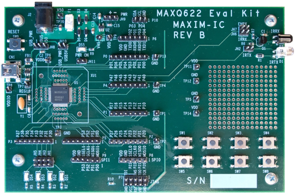 Figure 1. MAXQ622 EV kit.
The MAXQ622 EV kit board has a number of jumpers to configure. For this application note, the jumpers should be configured to match the default settings, as shown in Table 1.
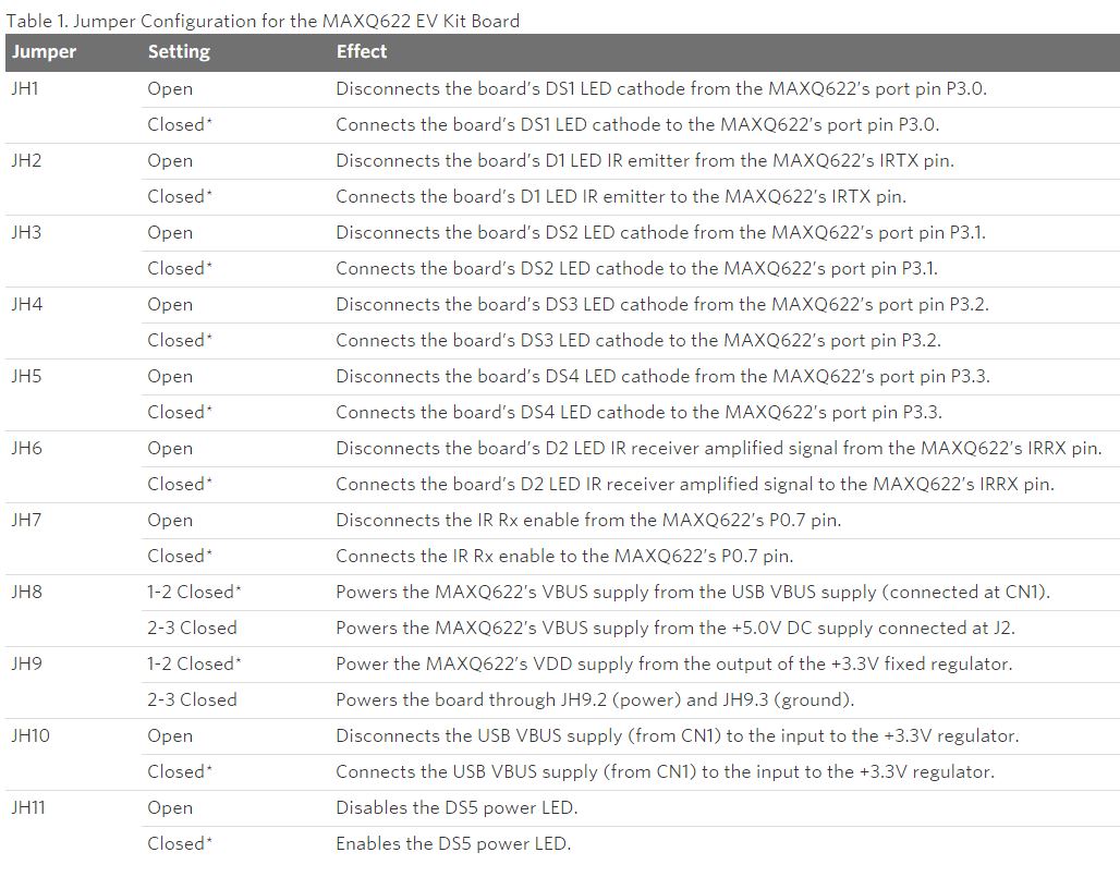 *Default settings.
A USB-to-JTAG/1-Wire adapter has been included with the EV kit to program the MAXQ622. The installation guide for the adapter is available for download.
After installing the USB-to-JTAG/1-Wire adapter, connect the JTAG cable to the MAXQ622 EV kit board. The red stripe on the cable should connect to the side of the connector labeled pin 1 and pin 2 on the JTAG board and to the side of the connector labeled TCK-GND on the MAXQ622 EV kit board.
Getting Started with the IAR Embedded Workbench
The IAR Embedded Workbench® is the primary IDE used for coding in C with the MAXQ622. The latest version can be obtained from the our website. IAR™ offers both time-limited and size-limited licenses of the IDE for evaluation. Download and execute the installer. Follow the directions to install the software.
After installing the software, open the application and create a new project in the current workspace. Ensure that the MAXQ tool chain is selected from the drop-down list, and open a new C project with a generated main.c file (Figure 2).
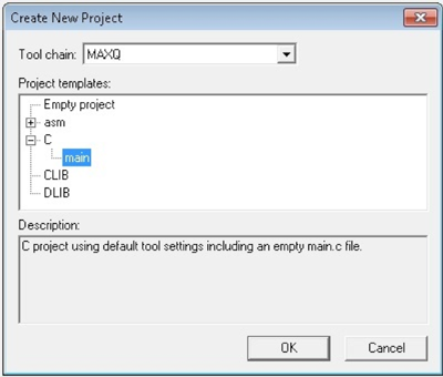 Figure 2. IAR new project wizard.
To configure the project to run on the MAXQ622, select Options from the Project menu or press ALT+F7. Select MAXQ622 from the device drop-down menu and ensure that CLIB is selected under the Library Configuration tab (Figure 3).
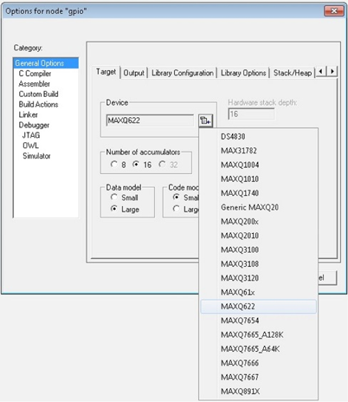 Figure 3. IAR Embedded Workbench project configuration.
Once the target device is selected, assign the com port that the JTAG adapter is using by inputting the string referencing the com port in the text field provided (Figure 4). Note: Use the System Device Manager to verify the com port setting.
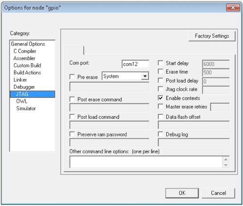 Figure 4. IAR JTAG settings.
The workspace maxq622evkit.eww includes sample projects that are viewable in the Workspace window. Configure each project in the workspace to match the MAXQ622 by following the above steps. The projects are now ready to be compiled, loaded, and debugged on the EV Kit.
Using IAR to Debug an Application
For this application note example, activate the gpio project from the Workspace tab and ensure that the project settings described above have been properly configured. To view the source code for the project, double-click on the file gpio.c. The file isr.c is not used in this project, but it contains the interrupt callback functions for other projects included with the EV kit. To begin debugging the project, click the Debug button or press Ctrl + D. This action automatically compiles the source code and loads it onto the MAXQ622. The default debug settings will automatically place a breakpoint at the main function (Figure 5).
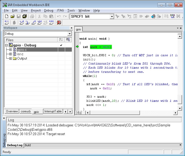 Figure 5. IAR debug.
From here, navigate through the program using the Debug toolbar functions. To set more breakpoints throughout the code, double-click in the margin to the left of the line to place a break in the program (Figure 6).
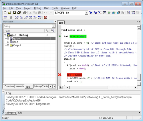 Figure 6. IAR breakpoints.
The gpio example uses a timer on the MAXQ622 to blink 4 LEDs. The first four pins are wired to these LEDs and can be manipulated by the software. By shifting the mask variable, the position of the high bit will move through the mask to the bit for each LED (Figure 6). The PD3 register controls the direction of the port 3 pins. Setting these bits to 1 configures them for output, allows the voltage to be raised high, and turns on the LEDs.
A timer in the MAXQ622 is then used to control the blink rate of the LEDs. The timer initializes to count at a constant rate (Sysclk/256) from 0 up to 0xB71B. The default Sysclk is 12MHz, making the timer raise its flag every second (Figure 7).
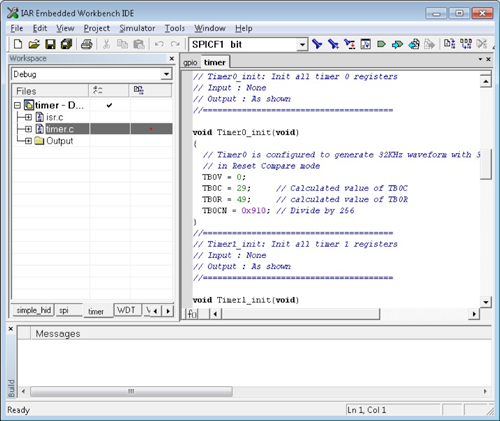 Figure 7. Timer Initialization.
The IAR software allows the user to view variable and register values while debugging. In order to look at a register or variable, right-click on the expression and select Add to Watch. When a breakpoint halts execution or the Break button is pressed, these values are updated and can be changed by the user (Figure 8). Also, view registers by selecting the View menu and clicking Register.
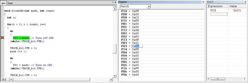 Figure 8. blinkLED() function/IAR Register and Watch.
1-Wire is a registered trademark of Maxim Integrated Products, Inc.
IAR Embedded Workbench is a registered trademark of IAR Systems AB.
IAR is a trademark of IAR Systems AB.
Related Parts
MAXQ622 16-Bit Microcontrollers with Infrared Module and Optional USB
Advertisement
Learn more about Maxim Integrated


