Helping prevent damage to USB Charger systems
The new USB protocols with increased data rates make low-capacitance ESD protection of the bus very important
BY KEDAR BHATAWADEKAR
Tyco Electronics
Raychem Circuit Protection Products
Menlo Park, CA
http://www.circuitprotection.com
The evolution of USB protocols such as USB Charger and USB 3.0 has increased the demand for more robust and reliable circuit protection techniques. As USB continues to increase its current-delivery capability, the need for new overcurrent protection solutions has intensified. The new USB protocols have also increased data-rate speeds and, to ensure data integrity between devices, have made low-capacitance ESD protection of the bus more important than ever.
The trend toward using USB’s power capabilities to charge batteries on portable devices has resulted in a demand for industry-standard approaches and has led to the new specifications being published by the USB-IF (USB Implementers Forum).
This development presents designers and manufacturers of portable devices with a challenge as well as an opportunity. The challenge is the need to meet all of the new USB specifications while keeping costs down. The opportunity is to improve the consumer experience via faster charging speed and universal charging.
The USB 2.0 specification identifies two types of power sources for battery charging: the dedicated charger (or wall charger) and the host or hub charger. The host and hub chargers use similar circuitry for charging and data enumeration. Because each of these power sources uses a mechanically identical connection even though their power characteristics are quite different power source detection is a critical design consideration.
USB devices (1.0 and 2.0) use four pins for connectivity: VBUS (+5 V), ground, Data and Data +. The VBUS and ground provide the power source for the connected device or the current/voltage for charging the connected device. D and D+ are the communication channels and adhere to very specific procedures for enumeration. Upon being attached to a host, hub, or USB charger, the portable device detects a voltage on the VBUS . The portable device must then determine what it is attached to, and limit its current appropriately.
Higher current, higher risk
Although power via USB has been in use for some time, the new standard dramatically increases the amount of current that can flow to a USB device to a new maximum current rating of 1.5 A (as compared to 0.5 A for USB 1.0 and 2.0). These higher-current applications require more reliable and robust circuit protection to help prevent damage caused by overvoltage transients and overcurrent conditions.
Overvoltage transients are generally a result of ESD and may occur on both the power bus as well as the data lines. Although modern ICs are protected to up to 2,000 V, a human body can easily build up static charge that ranges up to 25,000 V. In I/O port protection applications, a very-low-capacitance ESD device with fast clamping and recovery response is required on the data lines.
Overcurrent conditions can also affect the power bus. The circuit protection requirement here is the ability to handle inrush currents (up to 1.5 A per port for USB charging) reliably, and limit current faults below 5 A in 60 s in the event of a fault (UL 60950 Table 2C).
Protecting dedicated chargers
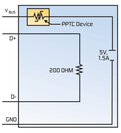
When a portable device is connected to a dedicated charger and detects that D+ and D are shorted, the device allows a maximum charging current of 1.5 A. A pure charging device, the dedicated charger only outputs power via the USB connector and is not capable of data communication. Figure 1 illustrates how a polymeric positive temperature coefficient (PPTC) device on the VBUS helps prevent overcurrent damage caused by a sudden short circuit downstream of the charger (that is, on the device side).
PPTC devices provide the resettable functionality, small size, fast time-to-trip, and low-power dissipation required in a wide variety of USB applications. They can help designers meet the new high-current requirements of the USB Charger specification and provide a simple, cost-effective solution for high-density circuit board designs.

Fig. 1. Overcurrent protection scheme for dedicated USB Charger.
Protecting host/hub chargers
In the case of host/hub chargers, the portable device may not cause the voltage to drop below 2.0 V under normal operating conditions. It must limit the amount of current drawn from a host/hub charger to 1.5 A at low speed or full speed or to 0.9 A at high speed.
PPTC devices help provide a cost-effective solution for meeting USB and UL60950 overcurrent protection requirements. In traditional USB applications with a 0.5 A current limit, up to four ganged ports can be protected with a single PPTC overcurrent protection device, and still supply 0.5 A per port with response to current over 5 A. USB charging must support 1.5 A per port and still respond to currents over 5 A, in order to meet UL60950 requirements. As such, it is recommended that each individual port include current-limiting circuitry.
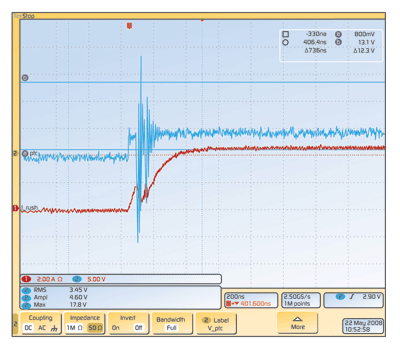
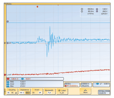
USB overvoltage protection devices designed for traditional 0.5-A ports may also be inadequate for the new USB Charger specification of 1.5 A per port. As shown in Figs. 2a and 2b , 1.5-A hot disconnects can generate significantly high inductive spikes that can affect the devices left on the bus. A well-designed bus will absorb these spikes and protect devices from exposure to them.

Fig. 2a. Typical overvoltage event in a USB 2.0, four-port ganged application.

Fig. 2b. Typical overvoltage event in a USB 3.0, two-port ganged application.
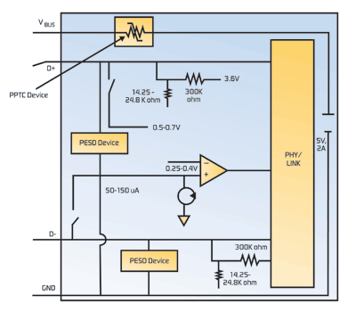
A coordinated circuit protection strategy for protecting host or hub chargers is shown in Fig. 3. The PPTC device helps protect against overcurrent damage on the VBUS line, and PESD devices are used to shunt ESD away from sensitive circuitry on the data lines. PESD devices provide low capacitance compared to traditional MLV (multilayer varistor) or TVS (transient voltage suppression) diode technology, and their low trigger voltage and low clamping voltage also helps protect sensitive electronic components.
PPTC devices help provide a cost-effective solution for meeting USB and UL60950 overcurrent protection requirements

Fig. 3. Host and hub chargers require coordinated overcurrent and overvoltage protection.
Overcharge considerations
As per the recommendations of IEEE 1725-2006 standard for rechargeable batteries in cellular telephones and the Cellular Telecommunications and Internet Association (CTIA), the maximum charging voltage and current should be set on the basis of agreements made among cell, battery pack and host device manufacturers and must be based on upper voltage and current limits of the cell, as specified by the cell manufacturer.
PPTC devices offer a cost-effective solution to help meet USB and UL60950 overcurrent protection requirements
Some high-volume manufacturers have indicated that they design their USB 2.0 systems to withstand up to 16 V (some systems must be designed to withstand up to 24 V) in order to minimize damage and returns caused by voltage transients. Due to the higher currents allowed in the USB charger specification, as well as increased potential for poorly regulated third-party chargers, designers may need to increase this value.
New charging technologies will enhance the convenience of portable electronic devices. However, these higher current applications will require more robust circuit protection to help prevent damage caused by overvoltage transients, and sustained overvoltage and overcurrent conditions. Protection requirements are application-dependent and designers must decide what level of protection is required for their application. Recommendations from device manufacturers are useful in narrowing protection options and benchmarking other port protection schemes may provide a good path for further investigation. However, specific testing of each protection option is the best way to evaluate its effectiveness. ■
For more on USB Charger systems, visit http://www2.electronicproducts.com/Power.aspx.
Advertisement
Learn more about TE Connectivity


