Attention musicians everywhere! You can make music much more original by making every note of it truly yours by creating your own custom musical instrument digital interface (MIDI) controller. How do you do such a thing, you ask? With the open-source electronic prototyping platform known as the Arduino.

Image source: MakeUseOf.
With an Arduino Uno, this project is simple and quick. If you’re unfamiliar with the Arduino, you should check out tutorials on how to use the board. If you’re experienced, get ready to tackle this design. But before beginning, be sure you know that there are two main types of MIDI messages: Control Change (CC) and Program Change (PC).
CC messages contain a controller number and a value between 0 and 127. These messages are typically used to change settings such as volume or pitch. Devices that accept MIDI should come with a manual explaining what channels and messages are set by default, and how to change them.
PC messages are simpler than CC messages. PC messages consist of a single number, and are used to change the preset or patch on a device. Like CC messages, manufacturers should provide a document outlining what presets are changed by a particular message.
Here’s what you’ll need to build your own MIDI controller:
- Arduino
- 5-pin DIN female socket
- 2 x 220 ohm resistors
- 2 x 10k ohm resistors
- 2 x momentary switches
- Hook-up wires
- Breadboard
- MIDI cable
- MIDI device or USB interface
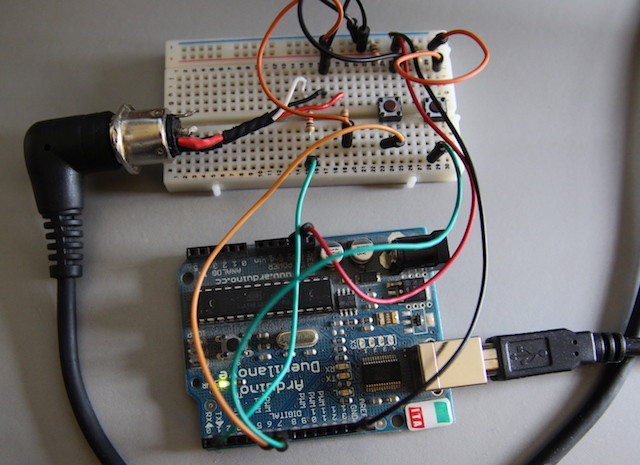
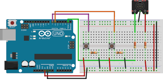
Once you have your equipment gathered, it’s time to begin. Because only three pins are needed, almost any Arduino is suitable. This project consists of two buttons to control the program, a MIDI port to send the data, and a device to receive the messages. In the original design, the circuit was built on a breadboard, but it’s possible to transfer it to a project box and soldered connectors for a robust solution.

Image source: MakeUseOf.

Image source: MakeUseOf.
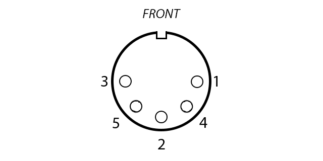
Take these steps to wire up your MIDI socket:
- MIDI pin 5 to Arduino Transmit (TX) 1 via a 220 ohm resistor
- MIDI pin 4 to Arduino +5V via a 220 ohm resistor
- MIDI pin 2 to Arduino ground
As for button connection, the buttons work by changing the resistance the Arduino sees. The Arduino pin goes through the switch straight to ground (LOW) via a 10k ohm resistor. When the button is pressed, the value seen by the circuit changes to +5v without a resistor (HIGH). The Arduino can detect this change using the digitalRead(pin) command. Connect the buttons to pins 6 and 7 on the Arduino digital input/output (I/O). Connect both buttons:
- Left side of button to +5V
- Right side of button to Arduino Ground via a 10k ohm resistor
- Right side of button to Arduino pin (6 or 7)
Once the hardware is finished, it’s time to get testing. You’ll need a USB-MIDI interface and a MIDI cable. The MIDI port wired on the breadboard will send data, so it functions as the output. Because your computer receives the data, it’s the input. This project uses the Arduino MIDI Library v4.2 by Forty Seven Effects. Once you have installed the Library, you can include it in your code by going to Sketch > Include Library > MIDI.
You’ll also need a program to monitor the incoming MIDI data:
- MIDI Monitor for OS X
- MIDI-OX for Windows
- KMidimon for Linux
Next, connect the Arduino to your computer and upload the following test code:
#include
#include
#include
#include
#include
MIDI_CREATE_INSTANCE(HardwareSerial,Serial, midiOut); // create a MIDI object called midiOut
void setup() {Serial.begin(31250); // setup serial for MIDI}
void loop()
midiOut.sendControlChange(56,127,1); // send a MIDI CC — 56 = note, 127 = velocity, 1 = channel
delay(1000); // wait 1 second
midiOut.sendProgramChange(12,1); // send a MIDI PC — 12 = value, 1 = channel
delay(1000); // wait 1 second}
This code will send a CC message. If everything is working correctly you should see a message appear in your MIDI monitor. If nothing happens, try troubleshooting:
- Ensure all the connections are correct
- Check the MIDI port is wired correctly – there should be 2 spare pins on the outside edges
- Double-check the circuit is correct
- Verify the circuit is connected to a USB-MIDI interface with a MIDI cable
- Check your MIDI cable is connected to the input on your USB-MIDI interface
- Make sure the Arduino has power
- Install the correct driver for your USB-MIDI interface
To be sure the buttons are working correctly, upload the following test code. Note that MIDI does not need to be connected to test this part.
const int buttonOne = 6; // assign button pin to variable
const int buttonTwo = 7; // assign button pin to variable
void setup() {Serial .begin(9600); // setup serial for text
pinMode(buttonOne,INPUT); // setup button as input
pinMode(buttonTwo,INPUT); // setup button as input}
void loop() {if(digitalRead(buttonOne ) == HIGH ) { // check button state
delay(10); // software de-bounce
if(digitalRead(buttonOne) ==HIGH) { // check button state again
Serial .println("Button One Works!"); // log resultdelay(250);}
if(digitalRead(buttonTwo) ==HIGH) { // check button state
delay(10); // software de-bounce
if(digitalRead(buttonTwo) ==HIGH) { // check button state again
Serial .println("Button Two Works!"); // log resultdelay(250);}
Run this code while keeping the USB cable connected, and open the Serial Monitor (Top Right > Serial Monitor). When you press a button you should see “Button One Works!” or “Button Two Works!” depending on which button you pressed.
When everything is wired and working correctly, you’ll assemble the full controller. The example below will send a different CC message for each button that’s pressed, and is similar to the testing samples above.
#include
#include
#include
#include
#include
const int buttonOne = 6; // assign button pin to variable
const int buttonTwo = 7; // assign button pin to variable
MIDI_CREATE_INSTANCE(HardwareSerial,Serial,midiOut); // create a MIDI object called midiOut
void setup() {pinMode(buttonOne ,INPUT ); // setup button as input
pinMode(buttonTwo,INPUT); // setup button as input
Serial .begin(31250); // setup MIDI output}void loop() {if(digitalRead(buttonOne ) == HIGH ) { // check button state
delay(10); // software de-bounce
if(digitalRead(buttonOne) ==HIGH) { // check button state again
midiOut .sendControlChange(56,127,1); // send a MIDI CC -- 56 = note, 127 = velocity, 1 = channeldelay(250);}
if(digitalRead(buttonTwo) ==HIGH) { // check button state
delay(10); // software de-bounce
if(digitalRead(buttonTwo) ==HIGH) { // check button state again
midiOut .sendControlChange(42,127,1); // send a MIDI CC -- 42 = note, 127 = velocity, 1 = channeldelay(250);}
And there you have it. There are plenty of uses for a MIDI controller — from a studio controller to a foot-controlled unit. Have you ever created your own custom MIDI controller? If so, leave a comment below.
Source: MakeUseOf
Advertisement
Learn more about Electronic Products Magazine


